All Categories
History
This section provides an overview for incremental encoders as well as their applications and principles. Also, please take a look at the list of 40 incremental encoder manufacturers and their company rankings. Here are the top-ranked incremental encoder companies as of August, 2026: 1.SHANGHAI QIYI CO.,LTD, 2.Hangzhou RoboCT Technology Development Co., Ltd., 3.Broadcom.
Table of Contents
Categories Related to Incremental Encoders
An encoder is a type of electronic component that uses a sensor to detect the amount, direction, and angle of mechanical movement and output them as electrical signals.
Encoders are divided into incremental encoders and absolute encoders, depending on the detection method.
An incremental encoder is an encoder that can measure the amount of change in position/rotation after the power is turned on. An absolute encoder can detect the absolute position/rotation from the origin even after the power is turned off.
With an incremental encoder, the absolute position cannot be determined unless a homing operation is performed after the power is turned off. The difference between incremental encoders and absolute encoders is whether this homing is required or not.
Incremental encoders are used as position/speed detectors in various machines, including:
Incremental encoders are often used as a component of motors. The encoder detects the direction and angle of rotation of a rotating shaft and uses the information for position and speed control of the motor.
Incremental encoders are divided into optical encoders and magnetic encoders, depending on the electrical detection principle.
The position detection principle of incremental encoders is explained using an optical encoder as an example.
An optical encoder mainly consists of a light emitter, a light receiver, and a disc (scale).
The disc (scale) has a slit engraved on it. As the disc rotates, light emitted from the light emitter repeatedly passes through and is blocked by the slit, thereby generating light pulses on the photosensor. The number of pulses output corresponds to the amount of movement of the slit, and the amount of movement can be detected by the number of pulses counted.
The slit is engraved with three types of slits: phase-A, phase-B, and phase Z. The light-receiving element detects these three types of pulses.
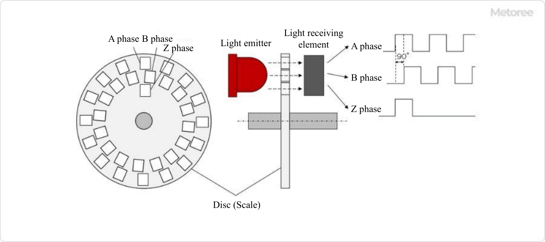
Figure 1. Optical incremental encoder configuration
There are two types of encoders: linear encoders, which detect linear movement, and rotary encoders, which detect rotational angles. Figure 1 uses a rotary encoder as an example, but the principle itself is the same for a linear encoder.
In a rotary encoder, slits are engraved on a disk-shaped disk, whereas in a linear encoder, slits are engraved on a rectangular-shaped scale like a ruler.
The rotational direction of FWD/REV can be detected by the order of the rising edges of the phase A and B pulses.
In FWD rotation, the rising edges of the phase A and B pulses are:
Phase A → Phase B → Phase A → Phase B → ...
Phase A→Phase B→Phase A→Phase B→...
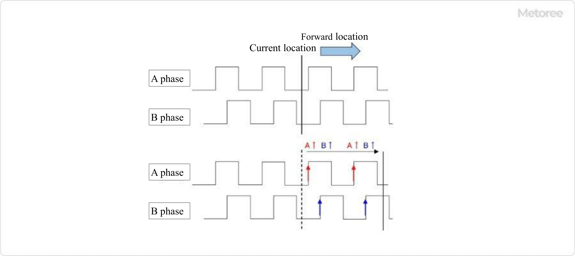
Figure 2. Detection order of phases A and B during forward rotation
In REV, the rising edges of the pulses of phases A and B are:
Phase B → Phase A → Phase B → Phase A → ...
Phase B -> Phase A -> Phase B -> Phase A -> ...
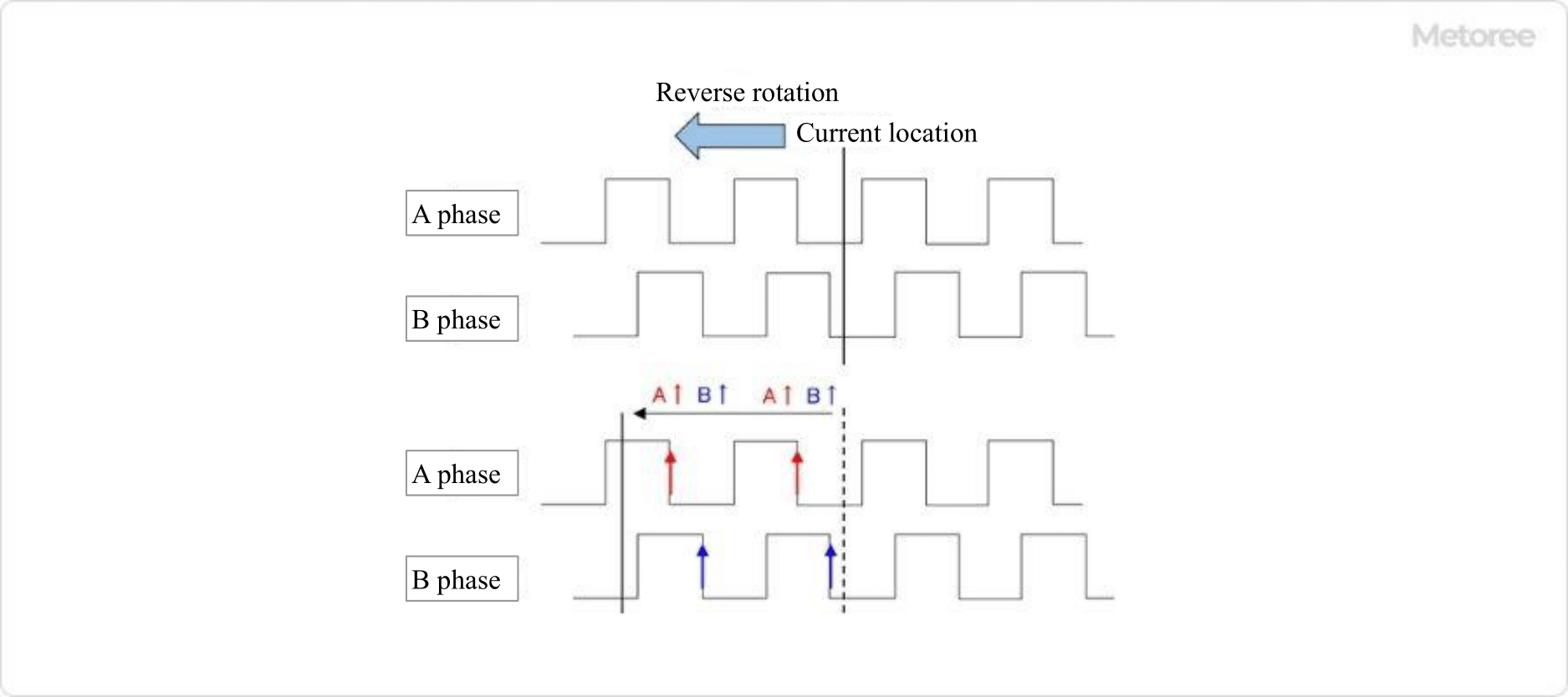
Figure 3. Detection order of phases A and B during reverse rotation
Since phases A and B are offset by 1/4 cycle, the direction of rotation can be determined by the order of the rising edges of the respective pulses.
The main specifications that can be used as an indicator when selecting an incremental encoder are as follows:
*Including some distributors, etc.
Sort by Features
Sort by Area

ifm efector (ifm) is a subsidiary of ifm electronic, founded in Germany in 1969. ifm has developed, manufactured and marketed sensors and controls technology to industries that include assembly and robotics, automotive, material handling, metal forming, mobile equipment, plastics, and food and beverage. Ifm produces sensors, condition monitoring equipment, image processing, safety technology, industrial communication, IO-link, systems for mobile machines, displays, software, connection technology, voltage supplies, as well as other accessories.
Sensata Technologies was originally founded in 1916 as General Plate Company and is now headquartered in Attleboro, Massachusetts. The company is a developer, manufacturer, and seller of sensors and sensor-rich solutions, electrical protection components, and other products used in automotive, industrial, energy, telecom, and construction industries. The company has 20 product categories including force sensors, tire management solutions, inverters & charges, and pressure sensors.The company’s next generation of products are designed to improve the efficiency of industrial pumps, fuel efficiency in ICE cars and energy efficiency in TVs, and facilitate usage of IoT devices.
Anaheim Automation is a manufacturer of motion control and automation products based in California since 1966. Their product list includes Stepper Motors and its Drivers, Controllers, Linear Actuators, and gearmotors that have applications in position control. There are also Brushless DC products, Servo motors, and systems, Integrated Circuits, AC Motors, and more that are necessary for equipment upgrades, process control, XY, and rotary tables, pump flow control, and material handling for industries that involve medical diagnostics, food, cosmetics, labeling, and robotics.
Pepperl+Fuchs, Inc. was founded in Mannheim, Germany in 1945 developing the forerunner of the proximity switch. Pepperl+Fuchs continues to develop proximity sensors as well as other industrial sensors including ultrasonic sensors, rotary encoders, positioning systems, display and signal processing, vibration monitoring, industrial communication, and signal processing as well as related accessories and software. Explosive protection products include safety barriers, surge protection, wireless solutions, HMI systems, power supplies, electrical explosion protection equipment, level measurement, and related software.
Celera Motion, founded in 1994 in the USA, is a motion control business of Novanta Inc. and a manufacturer of motion control devices and composite solutions for OEMs. The company's products, which include inductive encoders, direct-drive motors, servo drives, transducers, and air-bearing spindles, among others, are also used in the medical, Satcom, UAV, medical, and scientific markets. Celera Motion also offers ISO 9001 and ISO 13485-compliant encoders, motors, sensors, transducers, and servo drives in custom sizes.
CUI Devices, established in 1989 and headquartered in Lake Oswego, Oregon, is an electronic components manufacturer that is ISO 9001 certified. It stocks motion, sensor, and relay solutions and works with several distribution partners, including Mouser Electronics, Digi-Key Electronics, and Electro Sonic. The company gives back to the community by supporting organizations like Tualatin School House Pantry, Girls Who Code, and Friends of Trees, which aim to uplift society by providing basic needs, STEM education, and environmental stewardship. It has contract manufacturing facilities in other countries, including China, Vietnam, and Japan.
Sick AG, founded in 1946 and headquartered in Waldkirch, Germany, is a manufacturer of sensor and sensor solutions that aid in in production, logistics, and processes automation. The company’s expansive product portfolio includes industrial sensors, encoders, and analyzers. It has over 50 subsidiaries and equity investments as well as several agencies worldwide, and in the 2022 fiscal year, it generated around €2.2 billion. The company established the first subsidiary in France in 1972 and opened another subsidiary in USA in 1975. It changed to a joint stock company in 1996 and the first employee shares were issued in 1999.
Broadcom Inc., established in 1961, and headquartered in San Jose, California, is a manufacturer and supplier of semiconductor and connectivity solutions. The company specializes in producing products, such as semiconductors, infrastructure software, networking products, storage products, wireless products in which their products cater to industries such as telecommunications, data centers, and consumer electronics. Their products are used for various applications, including wireless communication, networking equipment, data storage, and multimedia devices, providing components for advanced technologies in numerous industrial and commercial sectors.
Phoenix America, founded in 2000 and based in Fort Wayne, Indiana, is a manufacturer and supplier of sensors, encoders, and technology. The company manufactures magnetic sensors, gear tooth sensors, hall commutators, anisotropic magnetoresistance (AMR) sensor chips, and elevator encoders, among other products. It also produces encoders and sensors for textile and paper processing machines. Its flow sensing sensors provide very clear visibility through non-ferrous objects and, when interfaced with a custom developed magnetic propeller, can sense through a plastic tube.
MSI Tec, Inc., established in 1983 and based in Centennial, CO, USA, is a manufacturer and supplier of automation machinery and systems. The company's product range includes precision motion control, intelligent machine control and operator interface systems, device networking for remote monitoring, and sensing technologies. These products facilitate tasks such as precise control, programming, sequencing, and sensing. It primarily serves industries like Automotive, Factory Automation, Food and Beverage, and Intelligent Transportation. Moreover, its services include OEM Computing Services, Networking Services, Robotics Solutions, and Subassembly Solutions.

B&Plus USA, Inc., formed in 1980 and headquartered in Ogawamachi, Japan, is a manufacturer of advanced electronic technologies and products for use in machining tools and other manufacturing equipment. The company specializes in making remote power supply, remote sensor systems, and remote coupler systems. It also crafts RFID systems, proximity switches, encoders, and guide sensors. Remote power supply, which is a system for remotely providing power, is used as a power source for a motor and to recharge the batteries of robots and automated guided vehicles.

Hangzhou RoboCT Technology Development Co., Ltd. (HRTD) is a Chinese manufacturer and supplier of robotic components and products that was established in Hangzhou in 2017. The company produces omni-directional mobile robots, mecanum wheels for robotic mobility, robot joint modules, and DC motors. It also offers contract manufacturing and technical support services for unique or demanding customer projects. HRTD serves a number of China’s institutions including the Shanghai Jiao Tong University, Beijing Institute of Technology, and the Zhejiang University Hospital, as well as clients in the chemical, logistics, and smart car industries.
Shanghai Qiyi Co., Ltd, headquartered in Shanghai, China, is a manufacturer of a range of sensors and industrial automation control products. The company makes shaft encoders, analog encoders, laser sensors, linear potentiometers, and shear beam load cells. It also creates reaction torque sensors, rotary torque sensors, load cell amplifiers, displacement indicators, and weather sensors. Its shaft rotary encoder is connected to the motor through a coupling and follows the motor to rotate synchronously to realize the detection of angle, position, and speed. All of the products it particularly manufactures have CE certificates.
YUEQING YUMO ELECTRIC CO.,LTD, founded in Zhejiang, China, in 2004 is a manufacturer of industrial automation control products. The company's product portfolio includes Programmable Logic Controller, Human Machine Interface, Photoelectric Switch, Proximity Switch, and Switching power supply. Their products find application in textile machinery Machinery, packaging machinery, wind power generation, and industrial assembly automation control field. The company serves industries such as Oil and Gas, Aerospace and Defense, Automotive and Transportation, Construction, and Power Generation.

FAULHABER, a manufacturer of high-precision miniature and micro drive systems, was founded in 1947 and is headquartered in Schönaich, in the German state of Baden-Wuerttemberg. Its main activity is the design, development, and manufacturing of precision miniature and micro-drive systems. The company offers a wide range of products, including DC motors, stepper motors, linear motors, and gearheads. FAULHABER's products are used by a wide range of customers, including medical device manufacturers, robotics companies, and automation systems integrators.

Puretronics is a manufacturer and distributor of electronic cleaning and maintenance products established in 2001 and based in Irvine, California, USA. The company’s product lineup includes precision contact spray cleaners for removing dust or particle buildup, cleaner degreasers for removing excess lubricant or residue, and technical-grade isopropyl alcohol for cleaning sensitive surfaces. It also offers solutions for cleaning plastic, glass, and sticker or label adhesive residue. The company’s products are used mainly by clients and individual consumers in the residential and commercial sectors.
The Kübler Group was founded in 1960, headquartered in Germany, and operating in 50 countries worldwide. The company is ISO 9001 certified and develops, produces, and distributes products & solutions for measurement, transmission, and evaluation purposes for heavy industry, bottling plants, alternative energy, and mobile automation. The company’s measurement products include data encoders, measurement systems, and inclinometers for measuring angles. Transmission products include slip rings, signal converters, and connectors. Evaluation products include process devices, displays and counters, and speed monitors.

Renishaw, founded in 1973, is a manufacturer and supplier headquartered in the UK, specializing in designing, developing, and delivering precise metrology technology systems and solutions. The company’s product portfolio includes metrology, position and motion control systems and healthcare applications. The company also offers additive manufacturing technology, producing industrial machines for metal 3D printing. The company’s solutions and products cater to diverse sectors including healthcare, oil and gas, petrochemical, energy, and more. With offices in 36 countries, Renishaw helps companies worldwide transform their manufacturing with their precision measurement and process control systems.
TR-Electronic, established in 1983 and based in Trossingen, Germany, is a manufacturer and supplier of encoders and components. The product portfolio includes a diverse range of rotary and linear encoders, customized sensor designs, compact drives, and other machinery components with automation. The products are used in various applications which include metal process, paper, logistics, storage, event technology, and renewable energies. All the company products are ISO certified with other certifications too.
Tamagawa Seiki was established in Japan on March 3, 1938, and it is a developer and manufacturer of high-precision control equipments. The company manufactures and develops products like rotary encoders, resolvers, servo motors, gyros, step motors, aerospace products, and space products. Some of their major clients include Mitsubishi Heavy Industries, Toshiba, Hitachi, Toyota, and Honda. Their featured products are the Non-shaking system and Optical level gauging system. This company also manufactures two and three-dimensional (spatial) position/angle sensors.
TR Electronic, established in 1984 in Trossingen, Germany, is a manufacturer of encoders and industrial automation equipment. The company specializes in absolute encoders, sensors, measuring technology, monitoring, and control systems, as well as machine lighting solutions. The product range includes several optimal-precision encoders and sensors for accurate position and measurement data. These devices offer stability, durability, and optimum-resolution output, making them essential components in manufacturing, automation, robotics, and automotive. The monitoring and control systems result in process optimization and efficiency.
Baumer Electric AG was founded in 1952 and is headquartered in the city of Frauenfeld, Switzerland. The ISO 9001 and ISO 14001 certified company provides sensor solutions for digitalization, packaging, railway, food and beverage, and pharmaceutical industries. A sample of the company’s sensor product listings includes object detection, distance measurement, force sensors, accessories, and connectivity devices. The company offers product support for setup and installation, product functionality, and optimized product usage.
Dynapar Corporation is an American manufacturer of motion feedback control products that was established in Gurnee, Illinois, in 1955 before its acquisition by the Fortive Corporation in 2016. The company primarily produces specialized resolver and rotary encoder models. These specialized models include incremental encoders, frameless resolvers, and resolver transducers. It also offers related accessories such as encoder testers, mounting brackets, and encoder cables. The company chiefly serves its clients in North America’s oil and gas, power generation, and metalworking industries.
Omron Corporation, started in 1933 and headquartered in Kyoto, Japan, is a manufacturer of automation components, equipment, and systems, and it developed the first contactless proximity switch in 1960. It has four domains, including industrial automation, electronic components, healthcare, and social systems, and it provides products and services in around 120 countries and regions. Some of its products include microsensing devices, access control systems, industrial robots, surveillance cameras, and blood pressure monitors. In 1971, it developed the first online cash machine, and in 1972, it established Japan’s first welfare factory.
Encoder Products Company (EPC), headquartered in Idaho, USA, has been a manufacturer of motion sensing devices since 1969. Its range of offerings include incremental encoders, absolute encoders, linear encoders, encoder modules, as well as encoder testers, and encoder accessories. These devices are used to convert physical motion into electrical signals that can be utilized for monitoring, control, automation, and feedback purposes in a wide range of industries and systems. For those requiring an ECCN classification, all the company's incremental rotary encoders are classified as EAR99. The company also provides custom solutions, technical support, and warranty services for its customers.
Tokyo Cosmos Electric Co., Ltd, also known as TOCOS, was established in 1957. TOCOS creates environmentally-friendly electronic components for automotive, agricultural, health care, entertainment, and home appliance industries. These components include capacitors, switches, optoelectronic devices, and potentiometers.
Koyo Electronics Co., Ltd. was founded in 1955 and began manufacturing and selling portable radios, and in 2022 the company name changed to JTEKT ELECTRONICS CORPORATION. Based on human respect, KOYO uses wisdom and imagination to provide good value and contribute to developing a safe and fulfilling society.

Scancon, founded in 1973 in Denmark, is a manufacturer and supplier of encoders and sensors. Its product portfolio includes a wide range of encoders such as rotary encoders, optical encoders, and magnetic encoders that are crucial for accurately measuring and monitoring the position, speed, and direction of moving parts in various systems. In addition it offers proximity sensors, capacitive sensors, inductive sensors used for detecting and converting physical parameters into electrical signals. The company serves various industries, including automation, robotics, and medical technology.
Kodenshi Corp. is an ISO 14001 and IATF 16949-certified manufacturer of optical devices that was established in 1972 in Kyoto, Japan. The company’s product lineup includes photointerrupters for sensing motion or positioning, photodiodes for converting light into electrical currents, and phototransistors for amplifying currents generated by photodiodes. It also offers encoders for converting motion into digital signals, and photo couplers for noise reduction or signal isolation. The company’s products are commonly used within the private security and transportation sectors, and have additional applications in the automotive industry.
Rockwell Automation, Inc. was founded in 1903 and is headquartered in Milwakee, WI. Rockwell Automation provides industrial automation and digital transformation solutions around the world. Rockwell Automation operates through their intelligent devices, software & control, and lifecycle services segments with both hardware and software products and services. The Intelligent Devices segment offers drives, motion, safety, sensing, industrial components, and configured-to-order products. The Software & Control segment provides control and visualization software and hardware, information software, and network and security infrastructure solutions. The Lifecycle Services segment provides consulting, professional services and solutions, and connected and maintenance services through independent distributors.
QUANTUM DEVICES, established in 1989 and based in Barneveld, WI, is a manufacturer and distributor of optoelectronic products. The company's product range includes Incremental Optical Rotary Encoders, QC201 Commutation Indicator, OPTOLAB/Line Drivers, Photodiodes, and Photodiode Resources and Facts. These products find applications in photosynthesis and photobiological research, as well as in biomedical instruments for measuring variables such as blood sugar levels and pulse rate. Serving the appliances, electrical, and electronics manufacturing industries, the company offers services like design, development, manufacturing, and distribution of optoelectronic devices.

POSITAL is a leading supplier of advanced industrial position sensors used in motion control and safety systems. The company is known for innovation in product design and manufacturing, as well as being a pioneer of Industry 4.0/IIoT. As a member of the FRABA group, POSITAL has a history dating back to 1918 and has played a significant role in the development of rotary encoders and other sensor products. POSITAL has a global presence with subsidiaries in Europe, North America, and Asia and works with sales and distribution partners worldwide.
Ranking as of August 2026
Derivation Method| Rank | Company | Click Share |
|---|---|---|
| 1 | SHANGHAI QIYI CO.,LTD |
6.1%
|
| 2 | Baumer |
4.6%
|
| 3 | SICK AG |
4.6%
|
| 4 | Hangzhou RoboCT Technology Development Co., Ltd. |
4.3%
|
| 5 | Broadcom |
4.3%
|
| 6 | Celera Motion |
4.3%
|
| 7 | ifm efector, inc. |
4.3%
|
| 8 | SCANCON Encoders A/S |
3.9%
|
| 9 | TR-Electronic |
3.6%
|
| 10 | Pepperl+Fuchs Inc. |
3.6%
|
Derivation Method
The ranking is calculated based on the click share within the incremental encoder page as of August 2026. Click share is defined as the total number of clicks for all companies during the period divided by the number of clicks for each company.Number of Employees
Newly Established Company
Company with a History
*Including some distributors, etc.
*Including some distributors, etc.
| Country | Number of Companies | Share (%) |
|---|---|---|
|
United States of America
|
10 | 34.5% |
|
Japan
|
6 | 20.7% |
|
China
|
5 | 17.2% |
|
Germany
|
4 | 13.8% |
|
India
|
1 | 3.4% |
|
United Kingdom
|
1 | 3.4% |
|
Denmark
|
1 | 3.4% |
|
Spain
|
1 | 3.4% |
636 products found
636 products

Midori Sokki Co., Ltd.
730+ people viewing
IncOder is a product of Celera MOTION (UK). Midori Sokki is a Japanese distributor. ■Features - Consists of a hollow ring-shaped stator and rotor....

Midori Sokki Co., Ltd.
450+ people viewing
Last viewed: 15 hours ago
■Product features A rotary optical incremental encoder that combines high resolution and robustness. Although compact, it uses high resolution and ...
9 models listed

POSITAL -Fraba
270+ people viewing
Last viewed: 14 hours ago
◾️Absolute Multi -Turn Kit Encoder/Inclumental Kit Encoder The Posital Kit Encoder offers smart, maintenance -free and costly solutions for the mo...
10 models listed
POSITAL -Fraba
310+ people viewing
◾️Absolute Multi -Turn Kit Encoder/Inclumental Kit Encoder The Posital Kit Encoder offers smart, maintenance -free and costly solutions for the mo...
10 models listed

Midori Sokki Co., Ltd.
440+ people viewing
Last viewed: 11 hours ago
■Product features A rotary magnetic absolute encoder designed to eliminate factors that degrade accuracy. It is a highly environmentally resistant ...
10 models listed

Midori Sokki Co., Ltd.
400+ people viewing
Last viewed: 13 hours ago
■Product features A rotary optical incremental encoder that combines high resolution and robustness. Although compact, it uses high resolution and ...
10 models listed

POSITAL -Fraba
380+ people viewing
◾️Absolute Multi -Turn Kit Encoder/Inclumental Kit Encoder The Posital Kit Encoder offers smart, maintenance -free and costly solutions for the mo...
10 models listed


POSITAL -Fraba
430+ people viewing
Last viewed: 1 day ago
◾️Absolute Multi -Turn Kit Encoder/Inclumental Kit Encoder The Posital Kit Encoder offers smart, maintenance -free and costly solutions for the mo...
10 models listed


POSITAL -Fraba
920+ people viewing
Last viewed: 19 hours ago
◾️Absolute Multi -Turn Kit Encoder/Inclumental Kit Encoder The Posital Kit Encoder offers smart, maintenance -free and costly solutions for the mo...

POSITAL -Fraba
260+ people viewing
Last viewed: 11 hours ago
◾️Absolute Multi -Turn Kit Encoder/Inclumental Kit Encoder The Posital Kit Encoder offers smart, maintenance -free and costly solutions for the mo...
9 models listed
POSITAL -Fraba
260+ people viewing
◾️Absolute Multi -Turn Kit Encoder/Inclumental Kit Encoder The Posital Kit Encoder offers smart, maintenance -free and costly solutions for the mo...
10 models listed

Panasonic Industry Co., Ltd.
560+ people viewing
■ Why fluid bearing cooling fans are chosen ・Quiet performance due to unique fluid bearing structure ・Contactless rotation keeps quiet even durin...

POSITAL -Fraba
540+ people viewing
Last viewed: 16 hours ago
◾️Absolute Multi -Turn Kit Encoder/Inclumental Kit Encoder The Posital Kit Encoder offers smart, maintenance -free and costly solutions for the mo...
10 models listed


POSITAL -Fraba
580+ people viewing
Last viewed: 14 hours ago
◾️ Programmable incrimental encoder The Inclumental Rotary Encoder emits output signals each time the shaft rotates a certain angle. The number (p...
10 models listed


POSITAL -Fraba
830+ people viewing
Last viewed: 28 minutes ago
◾️ Programmable incrimental encoder The Inclumental Rotary Encoder emits output signals each time the shaft rotates a certain angle. The number (p...
10 models listed


Coretech Co., Ltd.
500+ people viewing
The Ergo magnetic incremental linear encoder is a cylindrical encoder with a sensor and electronic circuit built into a cylindrical metal case, and...
3 models listed

POSITAL -Fraba
370+ people viewing
◾️ Programmable incrimental encoder The Inclumental Rotary Encoder emits output signals each time the shaft rotates a certain angle. The number (p...
2 models listed

POSITAL -Fraba
360+ people viewing
◾️ Programmable incrimental encoder The Inclumental Rotary Encoder emits output signals each time the shaft rotates a certain angle. The number (p...
2 models listed

POSITAL -Fraba
600+ people viewing
Last viewed: 1 day ago
◾️ Programmable incrimental encoder The Inclumental Rotary Encoder emits output signals each time the shaft rotates a certain angle. The number (p...
10 models listed


POSITAL -Fraba
840+ people viewing
◾️ Programmable incrimental encoder The Inclumental Rotary Encoder emits output signals each time the shaft rotates a certain angle. The number (p...
10 models listed


POSITAL -Fraba
590+ people viewing
◾️ Programmable incrimental encoder The Inclumental Rotary Encoder emits output signals each time the shaft rotates a certain angle. The number (p...
10 models listed


POSITAL -Fraba
680+ people viewing
Last viewed: 5 hours ago
◾️ Programmable incrimental encoder The Inclumental Rotary Encoder emits output signals each time the shaft rotates a certain angle. The number (p...
10 models listed


POSITAL -Fraba
310+ people viewing
◾️ Programmable incrimental encoder The Inclumental Rotary Encoder emits output signals each time the shaft rotates a certain angle. The number (p...
10 models listed


POSITAL -Fraba
300+ people viewing
◾️ Programmable incrimental encoder The Inclumental Rotary Encoder emits output signals each time the shaft rotates a certain angle. The number (p...
9 models listed


POSITAL -Fraba
290+ people viewing
◾️ Programmable incrimental encoder The Inclumental Rotary Encoder emits output signals each time the shaft rotates a certain angle. The number (p...
6 models listed


POSITAL -Fraba
630+ people viewing
Last viewed: 1 day ago
◾️ Programmable incrimental encoder The Inclumental Rotary Encoder emits output signals each time the shaft rotates a certain angle. The number (p...
10 models listed
POSITAL -Fraba
500+ people viewing
◾️ Programmable incrimental encoder The Inclumental Rotary Encoder emits output signals each time the shaft rotates a certain angle. The number (p...
9 models listed
POSITAL -Fraba
310+ people viewing
◾️ Programmable incrimental encoder The Inclumental Rotary Encoder emits output signals each time the shaft rotates a certain angle. The number (p...
6 models listed