All Categories
History
This section provides an overview for high voltage probes as well as their applications and principles. Also, please take a look at the list of 13 high voltage probe manufacturers and their company rankings. Here are the top-ranked high voltage probe companies as of July, 2026: 1.Rohde & Schwarz USA, Inc., 2.Pico Technology Limited, 3.Ross Engineering Corp..
Table of Contents
Categories Related to High Voltage Probes
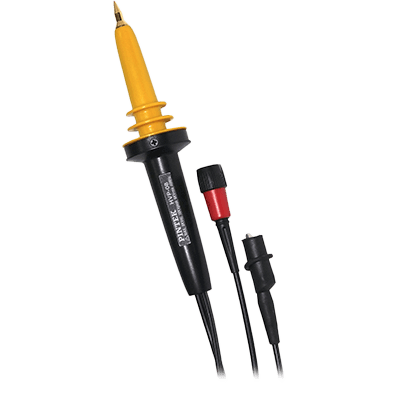
High voltage probes are passive probes capable of measuring high voltages.
In high voltage measurements that exceed several hundred volts, standard voltage probes will break down and cannot be used. General-purpose probes have difficulty handling high frequencies and high voltages. In contrast, high voltage probes can measure voltages as high as several thousand to several tens of thousands of volts and are passive probes dedicated to high voltages.
High voltage probes are used, for example, when measuring voltage waveforms by connecting them to an oscilloscope or other dedicated measuring instrument. When measuring large voltages at high frequencies, the probes quickly heat up, so care must be taken to avoid burns or electric shock.
High voltage probes are used to measure waveforms of high voltages of several hundred volts or more, and are often used to measure signals in motor drivers, switching power supplies, inverters, and converters that use power devices such as IGBTs (insulated gate bipolar transistors).
They are also often used in DC circuits and other situations where high voltage loads are possible. Other applications include measuring the anode voltage of cathode ray tubes as well as safety inspections of photovoltaic power generation equipment such as mega solar power plants without interrupting the grid, and measurements of high-voltage electrical systems used in hybrid and electric vehicles.
When selecting a probe, consider the frequency bandwidth, input resistance, input capacitance, operating voltage range, and compatible oscilloscope model.
High voltage probes measure high voltages by dividing them by the ratio between the internal resistance of the oscilloscope or other measurement device and the probe's magnification resistance. When measuring high voltages, a high voltage probe with an attenuation ratio of 100:1 or 1,000:1 is used.
The probe is used to physically and electrically connect the test point, or signal source, to the oscilloscope. The maximum allowable voltage of the voltage probe must be checked for rating due to its tendency to decrease with increasing frequency.
Specifically, the probe is placed between the input terminal and the oscilloscope input section, and the waveform passing through it is measured. When measuring high-frequency signals, the input capacitance becomes a load and affects the signal. However, by connecting through a probe with a high attenuation ratio, a more accurate waveform can be measured.
The construction of high-voltage probes varies depending on the voltage range to be measured. Products with a DC voltage of about 25KV sold by oscilloscope manufacturers can be handled by the user in the same way as general probes.
A high voltage probe consists of a probe body, a matching box, and a cable connecting them. The inside of the probe is filled with insulating oil or gas to enhance withstand voltage performance. The input resistance of the probe body depends on the attenuation of the attenuator, but a large value of 100 to 1,500MΩ is used.
The matching box performs phase compensation, and the adjustment procedure is more complicated than for ordinary passive probes because of the large attenuation of the attenuator and the use of long cables. In some cases, manufacturers of high voltage probes ship them adjusted and forbid the user to adjust them.
Since high-voltage probes handle high voltages, various safety measures are taken, such as the following:
An isolated probe is one in which only the probe is floating. It is electrically isolated from the oscilloscope body.
There are two ways to isolate the probe: one is to use a transformer to separate the probe tip from the oscilloscope, and the other is to convert the electrical signals received at the probe tip to photoelectric signals, transmit them through an optical fiber, and return them to the original signals at the receiver side. In both cases, there is no electrical continuity between the probe and oscilloscope. They are insulated from each other, but the signal detected by the probe is transmitted to the oscilloscope side.
Because of this configuration, even though the oscilloscope itself is properly grounded, it has no effect on the signal of the circuit under test that is applied between the tip of the isolated probe and the ground lead. Thus, even if the circuit under test has a very high common-mode voltage, the isolation probe can be used to measure only the differential voltage between the tip and ground lead.
*Including some distributors, etc.
Sort by Features
Sort by Area

Rohde and Shwarz, headquartered in Munich, Germany, is a technology business that creates, develops, and promotes innovative information and communication technology products for professionals. Customers all over the world rely on Rohde & Schwarz and its cutting-edge solutions in the test & measurement, secure communications, networks & cybersecurity, and broadcast & media areas. They were created in 1993 and have regional hubs in Asia and the United States.Rohde & Schwarz has invested heavily in emerging technologies such as artificial intelligence, the industrial internet of things (IIoT), 6G, cloud solutions, and quantum technology.
Ross Engineering Corporation, founded in 1964 and based in Campbell, California, is a manufacturer of a wide range of high-voltage electronic and electro-mechanical devices and is ISO 9001 certified. It stocks over 25 lines of high voltage devices such as voltmeters, relays, and probes used in several fields such as industrial plants, communication transmitters, and power supplies with ranges from 0.01mV to 1,200,000 V. The company is ISO/IEC 17025:2017 certified and has a calibration lab for testing and calibrating dividers, relays, and probes up to 450kV.
Teledyne LeCroy was founded in 1964 and is headquartered in Chestnut Ridge, New York, with sales, service, and development subsidiaries in the US and throughout Europe and Asia. The company serves a wide variety of industries including semiconductor & computer, consumer electronics, automotive, and telecommunications. The company’s product categories include oscilloscopes, electronic test equipment, protocol analysis solutions such as SATA and USB devices, modular data acquisition devices, and sensors and calibrators. The company provides services such as SSD testing, automotive and device interoperability testing, and technology training.
Keysight Technologies, Inc. was founded in 1939 and headquartered in Santa Rosa, California. Keysight is a global developer and manufacturer of electronic design and test solutions to communications, networking, aerospace, defense, and government, automotive, energy, semiconductor, electronic, and education industries. Keysight’s communications solutions group solutions include electronic design automation software; radio frequency and microwave test solutions, hardware and virtual network test platforms and software applications, as well as optical laser source solutions. Keysight’s electronic industrial solutions group offers various design tools and verification tools. Keysight offers product support, technical support, and training and consulting services. It sells its products through direct sales force, distributors, resellers, and manufacturer's representatives.

Japan Finechem Co.,Inc. manufactures fine and speciality chemicals and industrial electronic components. The company was founded in Tokyo, Japan in 1959 and presently employs 272 employees overall Japan. Their product portfolio for chemicals includes organic and inorganic chemicals, intermediates for food additives and pharmaceuticals, agricultural chemicals and feed additives. In the electronic components sector they manufacture electric machinery equipment and parts such as resistors and resistor boxes. They also produce high voltage measuring devices such as digital meters, probes and dividers. These products are mainly used in industrial equipments, chemical measuring instruments, X-ray apparatuses and electron microscopes.
Yokogawa Test & Measurement Corporation was founded in Japan in 1954. Yokogawa currently serves a wide array of industries including the aerospace, automotive, consumer electronics, semiconductor and telecommunications industries with both hardware and software solutions. Among Yokogawa’s suite of products are oscilloscopes, voltage probes, power analyzers and meters, data acquisition tools, optical test equipment, a wide variety of handled meters, calibrators, and testers; analog instruments, and manometers.

RIGOL, established in 1998, has its R&D headquarters in China and is a manufacturer of electronic test equipment with over 400 employees serving more than 60 countries and regions worldwide. The company's main products include digital and mixed-signal oscilloscopes, spectrum analyzers, RF signal generators, waveform generators, sensitive measurement products, and data acquisition systems. RIGOL's products are used for IoT, EMC pre-compliance solutions, spectrum monitoring, RF device characterization, and complex demodulation by commercial and industrial clients.
OWON - Fujian Lilliput Optoelectronics Technology Co., Ltd is based in China since 1990 as a manufacturer and supplier of test and measurement equipment. The company produces Digital Oscilloscopes available as handheld, virtual, tablet, and benchtop types as well as probes. They have Single Channel and Dual Channel Waveform Generators, along with Digital Multimeters and Programmable DC series Power Suppliers. There are also different types of Thermal Imagers, Spectrum Analyzers, and Anenmo Meters that can provide more than one kind of measurement.
TEKTRONIX, INC., founded in 1946, is a manufacturer of measurement solutions used in 3D sensing, EMI/ EMC testing, high-speed serial communication, material science engineering, and Wireless & RF testing. The products include oscilloscopes & probes, signal generators, margin testers, multimeters, and analyzers. The company's products are used in advanced research, aerospace & defense, automotive, power semiconductor, and medical industries. The Bracknell Berkshire company offers calibration, repair, asset management, package assembling, and testing services following NEMA, HAlT & HASS, environmental, and shock-vibration testing.

Sames has been a manufacturer and supplier of application equipment since 1925 and is headquartered in Meylan, France. The company's product range includes Airsprays, Airmix, Airless, Electrostatic and powder coating and high-viscosity solutions. These products are further classified into manual and automatic guns, pumps, regulators, machines, and controllers which have diverse uses in Transportation such as railways, cargo, tankers, truck cabs, road rails, etc. They are used by various other industries for finishing and protection applications and in the field of woodwork for bonding, polishing, and finishing furniture. The construction, automotive, and agricultural markets also benefit from Sames' products.
TEXIO TECHNOLOGY CORPORATION has been in operation in Japan for over 60 years. TEXIO specializes in custom orders of a variety of different products including power supplies. TEXIO also specializes in DC power supplies, oscilloscopes, multimeters, function generators, and safety testers.

Pico Technology was established in 1991 and is headquartered in St Neots, Cambridgeshire, United Kingdom where it designs, manufactures, and supplies PC-based test and measurement instruments. The company deals in data acquisition, oscilloscopes, and automotive diagnostics with various test and measurement instruments, including oscilloscopes, data loggers, spectrum analyzers, signal generators, and automotive diagnostics tools. The products help engineers, scientists, researchers, and technicians capture, analyze, and interpret signals and data in various applications. The company also collaborates with academic and research organizations besides aerospace, telecommunications, electronics, and manufacturing industries.
Ranking as of July 2026
Derivation Method| Rank | Company | Click Share |
|---|---|---|
| 1 | Rohde & Schwarz USA, Inc. |
15.3%
|
| 2 | Ross Engineering Corp. |
11.9%
|
| 3 | Pico Technology Limited |
11.9%
|
| 4 | Fujian Lilliput Optoelectronics Technology Co., Ltd. |
11.9%
|
| 5 | Keysight Technologies |
10.2%
|
| 6 | Teledyne LeCroy |
10.2%
|
| 7 | TEKTRONIX, INC. |
10.2%
|
| 8 | Sames |
8.5%
|
| 9 | IGOL TECHNOLOGIES, INC. |
3.4%
|
| 10 | Yokogawa Test & Measurement Corporation |
3.4%
|
Derivation Method
The ranking is calculated based on the click share within the high voltage probe page as of July 2026. Click share is defined as the total number of clicks for all companies during the period divided by the number of clicks for each company.Number of Employees
Newly Established Company
Company with a History
*Including some distributors, etc.
*Including some distributors, etc.
| Country | Number of Companies | Share (%) |
|---|---|---|
|
United States of America
|
4 | 33.3% |
|
Japan
|
4 | 33.3% |
|
China
|
2 | 16.7% |
|
France
|
1 | 8.3% |
|
United Kingdom
|
1 | 8.3% |
72 products found
72 products

Japan Finechem
650+ people viewing
Last viewed: 1 day ago
This instrument is a passive probe that connects to an oscilloscope and measures high voltage waveforms. The inside of the main unit uses an insula...

M.E. Co., Ltd.
1060+ people viewing
■Summary The world's only IsoVu probe has evolved even further. The size has been reduced to 1/5, and the performance and ease of use have also be...

Nisshinbo Micro Devices Inc.
970+ people viewing
Last viewed: 16 hours ago
■Summary R3121 is a voltage detector with a maximum input of 36V (absolute maximum rating: 50V). VDD terminal detection type (R3121NxxxA), SENSE te...

IGOL TECHNOLOGIES, INC.
360+ people viewing
Last viewed: 15 hours ago
■Product features ・RP1025D: 25MHz, maximum voltage ≦1,400Vpp ・RP1050D: 50MHz, maximum voltage ≦7,000Vpp ・RP1100D: 100MHz, maximum voltage ≦7,000...
4 models listed


M.E. Co., Ltd.
1150+ people viewing
■Summary The world's only IsoVu probe has evolved even further. The size has been reduced to 1/5, and the performance and ease of use have also be...

Nisshinbo Micro Devices Inc.
1010+ people viewing
Last viewed: 1 day ago
■Summary The R3119 series is a CMOS voltage detector IC that can operate up to 36V. It has a 36V input (absolute maximum operating rating of 50V) a...

Nisshinbo Micro Devices Inc.
880+ people viewing
Last viewed: 1 day ago
■Summary The R3154 is a window voltage detector that is ideal for meeting functional safety requirements. It monitors the drop/rise in the output v...

M.E. Co., Ltd.
1190+ people viewing
■Summary The world's only IsoVu probe has evolved even further. The size has been reduced to 1/5, and the performance and ease of use have also be...

M.E. Co., Ltd.
1380+ people viewing
■Summary The world's only IsoVu probe has evolved even further. The size has been reduced to 1/5, and the performance and ease of use have also be...


M.E. Co., Ltd.
1320+ people viewing
Last viewed: 1 day ago
■Summary The world's only IsoVu probe has evolved even further. The size has been reduced to 1/5, and the performance and ease of use have also be...

M.E. Co., Ltd.
1250+ people viewing
■Summary The world's only IsoVu probe has evolved even further. The size has been reduced to 1/5, and the performance and ease of use have also be...

Nisshinbo Micro Devices Inc.
830+ people viewing
Last viewed: 1 day ago
■Summary The R3151 series is a CMOS voltage detector IC that can operate up to 36V. It has a 36V input (absolute maximum operating rating of 50V), ...


Nisshinbo Micro Devices Inc.
850+ people viewing
Last viewed: 1 hour ago
■Summary The R3150 series is a CMOS voltage detector IC that can operate up to 36V. It has a 36V input (absolute maximum operating rating of 50V), ...

Nisshinbo Micro Devices Inc.
890+ people viewing
Last viewed: 12 hours ago
■Summary The R8300 series is an automotive CMOS voltage detector IC that can operate up to 36V. It has a 36V input (absolute maximum operating rati...

Nisshinbo Micro Devices Inc.
940+ people viewing
Last viewed: 1 day ago
■Summary The R3120 series is a CMOS voltage detector IC that can operate up to 36V. It has a 36V input (absolute maximum operating rating of 50V) a...

Nisshinbo Micro Devices Inc.
920+ people viewing
Last viewed: 1 day ago
■Summary R3152 is a window voltage detector ideal for functional safety requirements. It monitors drops and rises in the output voltage of the powe...

Nisshinbo Micro Devices Inc.
970+ people viewing
Last viewed: 1 day ago
■Summary R3500 is a 4ch window voltage detector with manual reset function that is ideal for systems with functional safety requirements. It monito...


IGOL TECHNOLOGIES, INC.
350+ people viewing
Last viewed: 15 hours ago
■Product features ・RP7080S: DC ~ 800MHz ・RP7150S: DC ~ 1.5GHz ・30V peak (CATⅠ) ・Compatibility: MSO/DS7000, MSO8000 series
2 models listed

Nisshinbo Micro Devices Inc.
1170+ people viewing
Last viewed: 12 hours ago
■Summary R3160 is a voltage detector with maximum input of 60V, high accuracy, and low current consumption. It can be used to directly monitor volt...

IGOL TECHNOLOGIES, INC.
360+ people viewing
Last viewed: 12 hours ago
■Product features ・RP7080: DC ~ 800MHz ・RP7150: DC ~ 1.5GHz ・30V peak (CATⅠ) ・Compatibility: MSO/DS7000, MSO8000 series
2 models listed

T&M Corporation Co., Ltd.
420+ people viewing
■Summary 50MHz, DC+AC (Peak): 40KV CATⅡ, AC (rms): 0~27KV CATⅡ

T&M Corporation Co., Ltd.
410+ people viewing
■Summary 100MHz, DC+AC (Peak): 18KV CATⅡ, AC (rms): 0~12KV CATⅡ

T&M Corporation Co., Ltd.
520+ people viewing
Last viewed: 10 hours ago
■Summary 50MHz, DC: 0~10KV, AC (rms): 0~7KV, Vpp: 0~20KV (Plus)

T&M Corporation Co., Ltd.
570+ people viewing
Last viewed: 9 hours ago
■Summary ・Oscilloscope high voltage probe Model P2300C bandwidth ・IMPUT Resistals100x with 300MHz rise time 1.15ms attenuation rate RatioFixed100...

T&M Corporation Co., Ltd.
530+ people viewing
Last viewed: 3 hours ago
■Summary ・Model: P4250 ・Attenuation ratio: 100X ・Input resistance: 100MΩ ・Input capacitance: 100X: 18.5pF ~ 22.5pF ・Compensation range: 15pF t...


