All Categories
History
This section provides an overview for ceramic capacitors as well as their applications and principles. Also, please take a look at the list of 20 ceramic capacitor manufacturers and their company rankings. Here are the top-ranked ceramic capacitor companies as of August, 2026: 1.Johanson Dielectrics, Inc., 2.Frontier Electronics Corp., 3.KEMET.
Table of Contents
Categories Related to Ceramic Capacitors
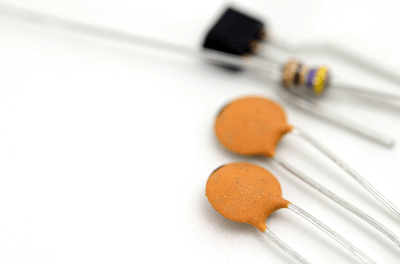
A ceramic capacitor is a capacitor that uses ceramic as the derivative.
The capacitor consists of two metal plates and a derivative sandwiched between the metal plates. Several materials are used As a derivative of the capacitor, each with its own characteristics.
Ceramic capacitors are characterized by their high dielectric constant, small size, and heat resistance. Furthermore, as capacitors with good frequency characteristics, they are often used in high-frequency circuits.
Ceramic capacitors are used as bypass capacitors in digital circuits. A capacitor is characterized by its ability to pass AC current but not DC current.
Ceramic capacitors are used as coupling capacitors or line filters because of their ceramic properties. Examples include AC/DC and DC/DC converter circuits and circuits for circuit breakers.
They are also widely used to cancel high and low frequency noise.
The principle of a ceramic capacitor is the same as that of a general capacitor. In principle, a ceramic dielectric is placed between two electrodes, and when a voltage is generated between the electrodes, electric charge is stored in the electrodes. Thereafter, the stored electric charge is released as charge by the capacitor.
The capacity of the charge stored by a capacitor is called capacitance. The capacitance and its properties vary depending on the material of the dielectric, the distance between the electrodes, and the number of dielectric layers.
Ceramic derivatives with high inductivity are used. The main materials used are titanium dioxide and alumina. Barium titanate is also used, but it is slightly more expensive. Although expensive, Barium titanate capacitors have higher capacitance.
Ceramic capacitors are classified into three main types, namely: low dielectric constant type, high dielectric constant type, and semiconductor type.
Titanium dioxide is used as the main dielectric. It is resistant to temperature change, used for coupling and for temperature compensation.
Barium titanate is used as the dielectric, and its dielectric constant is higher than that of titanium dioxide. It has a high capacitance and is used for smoothing circuits. However, it is somewhat expensive.
Semiconductor type uses semiconductor ceramics such as strontium titanate as the dielectric. It is considered a compact capacitor with large capacitance and good insulation properties. It is the most expensive of the three.
Ceramic capacitors do not directly state their capacitance such as "0.1 uF" or "10 uF" due to their small body size, but only use 1 to 3 digits to indicate the capacitance.
In the Case of 1 to 2 Digits
In the case of 1- to 2-digit numbers, the capacitance is simply the number read as it is and the unit of "pF (picoFarad)" is added. For example, "5" is 5pF and "33" is 33pF.
The smaller the number, the smaller will be the capacitance, while the smaller the capacitor, the smaller the size of the body.
In the case of 3 digits
In the case of 3-digit capacitors, as with carbon film resistors, the upper two digits are read as numerical values, while the third digit is multiplied as a multiplier. The unit is also "pF". For example, "104" is 10 x 10 to the 4th power = 100000pF = 100nF = 0.1uF, and "223" is 22 x 10 to the 3rd power = 22000pF = 22nF = 0.022uF.
On the other hand, many chip-type ceramic capacitors do not indicate the capacitance on the body. It is recommended to check the capacitance with a tester capable of measuring capacitance before mounting or replacing parts, such as removing the capacitor from the tape just before use or storing it in a case that can be divided into smaller pieces.
In general, ceramic capacitors have no polarity and can be mounted in either direction in a circuit. In the case of leaded components, since the capacitance is printed on only one side, the sides with the capacitance printed on them should basically face the same direction.
If there are taller components nearby, mount them in an orientation that allows the values to be read later, so that the board is easy to see when checking.
Ceramic capacitors have an upper limit for the voltage that can be applied. However, depending on the size and rating of the capacitor itself, it may not be specified on the body or may be specified as an abbreviation.
When using capacitors in circuits that handle particularly high voltages, please check the data sheet or manufacturer's model number carefully. This is because the manufacturer's model number, which is a long list of alphanumeric characters, may contain information on withstand voltage.
*Including some distributors, etc.
Sort by Features
Sort by Area

WIN SOURCE is meticulously amassing electronic components, through refined procedures, first-rate services, diverse portfolios, intellectual investments, and expanding business globally. It caters to regular parts costdown needs, and obsolescence management, and focusing on customer satisfaction, offers a seamless, customized approach to optimize your supply chain, and experience supply chain solutions precisely designed to align with your unique needs, ensuring efficiency, flexibility, and cost-effectiveness. Web:win-source.net | win-source.group Email:service@win-source.net Global Branches :United States | Germany | Canada | Italy | Singapore | India | Japan | United Kingdom | South Korea | Hong Kong | Mainland China | Philippines

Frontier Electronics Corp., founded in 1972 and based in Simi Valley, California, is a manufacturer of passive components like diodes, MLCC capacitors, and magnetics such as air coils and transformers. The company can also provide customer-specific solutions, including manufacturing new components and technology or redesigning obsolete products to facilitate current manufacturing standards. It is ISO 9001 and IATF 16949 certified, and all its standard products are RoHS compliant. It is also WBENC-certified and ITAR-compliant and partners with several distributors like NRC, Chiptronics Inc., and Digi-Key Electronics.
KEMET has a portfolio of over 1,600 patents serving the automotive, aerospace, industrial, telecommunications, computing, consumer, and medical devices. KEMETs devices provide filtering, sensing, energy storage, power conversion, and haptic actuator technology. Among these devices are capacitors, electromagnetic compatibility (EMC) components, resistors, circuit protection devices, inductors, sensors, Piezoelectric devices, release, transformers, and engineering kits.
TQ Abrasive Machining (TQAM) is an American contract manufacturer specializing in ceramic machining services that was established in Santa Ana, California in 1994. The company offers various ceramic design and fabrication capabilities, including CAD/CAM design and prototype development, as well as machine slotting, press machine extrusion, hole drilling, and grinding. These are geared to the production of medical ceramic parts, vacuum tubes, insulator rods, and ceramic tiles, among others. TQAM mainly serves clients in the biotechnology, medical, semiconductor, and consumer electronics industries.
Massachusetts Bay Technologies, established in 1999, and based in Stoughton, Massachusetts is a manufacturer and supplier of semiconductors and capacitors. The product portfolio includes diverse range of microwave silicon diodes, ceramic capacitors, and thin film products. The products are used in different types of industries such as academic, university, and laboratory research, consumer products, telecom, military, and space. The company offers ISO-certified products with high-reliability systems, design development, product performance, and quality control.
CalRamic Technologies LLC, founded in 2002 with headquarters in the USA, is a specialist manufacturer of ceramic capacitors. The company's range of products includes HV MLC leaded capacitors for space applications, HV leaded disc capacitors for commercial applications, HV leaded disc capacitors for military applications, and HV chip capacitors for military applications. CalRamic Technologies LLC serves the military, telecommunications, consumer products, and many other industries. The company also provides customized design, engineering, and production of custom products to meet client-specific requirements.
Johanson Dielectrics Inc, established in 1993, and based in California, USA, is a manufacturer and supplier of capacitors. The product portfolio includes a diverse range of capacitors which are ceramic SMT, lead high voltage and high temperature, dual and multi capacitor, low inductance, arrays, and switch mode. All the products are ISO-certified and safety certified. The products are used in various industries which include electrical circuits, power supply, automotive, and energy management.
Knowles Precision Devices, founded in 1985 in the USA, is a specialty component manufacturer of a wide variety of capacitors, microwave to millimeter wave components, thin film capacitors, and substrates. The company's performance microelectronics products include multi-layer ceramic capacitors, single-layer capacitors, trimmers, mm-wave filters, and resonators for use in critical applications in the military, medical, electric vehicle, and 5G market segments. Examples include radar, pacemakers, MRI equipment, electric vehicles, and mobile phone base stations.
Vishay Intertechnology, Inc. (Vishay) was incorporated in 1962 and is headquartered in Malvern, Pennsylvania. The company serves the industrial, automotive, telecommunications, consumer products, and medical end markets and sells its products under numerous brand names inlcuding Siliconix, Draloric, Beyschlag, UltraSource, and Applied Thin-Film Products. The company manufactures and sells discrete semiconductors and passive electronic components in globally while operating in six market segments: MOSFETs, diodes, optoelectronic components, resistors, inductors, and capacitors.
NIC Components Corp., and Nippon Industries Co. Ltd. have collaborated for over 37 years to design and manufacture passive components, including capacitors, resistors, and magnetics. Established in the USA in 1982, NIC has expanded its business to the custom speciality that meets the demands of today’s emerging and latest technology. Their regional offices can be found in Canada, Malaysia, India, Mexico, China, etc. All of their products are built with more features and are certified with different ISO certifications. They also assist their customers in component selection through live support.

Tecdia Inc, a company located in Campbell, California, and was established in 1985, is a manufacturer of electronic components such as ceramic capacitors, resistors, and inductors for various industries including medical, automotive, and telecommunications. Its main headquarters is located in Tokyo, Japan. Some of their products include high-frequency ceramic capacitors for RF applications, high-voltage ceramic capacitors for power supply applications, and thin-film resistors for precision applications. Tecdia Inc is ISO 9001 certified and is engaged in contract manufacturing services centered on electronic equipment in Cebu, Philippines.
TDK Corporation, established in 1935, is a manufacturer of electronic solutions for the smart society based in Tokyo, Japan. The company is a part of the TDK Group, which has over 250 locations in more than 30 countries worldwide and employs over 103,000 people. They offer a wide range of products, including sensors, power supplies, and magnetic application products. The robotics industry is evolving at a rapid pace, and they are now offering , a robot development platform equipped with a variety of sensors essential to the accurate operation of robots, enabling more efficiency across a wide range of robot development.

HVC Capacitor Manufacturing, founded in 1999 and headquartered in Shenzhen, China, stands as a manufacturer of high voltage ceramic capacitors and resistors. Its product range includes high voltage ceramic capacitors for power supplies and motors, high voltage resistors for surge protection, doorknob capacitors for switchgear applications, screw terminal capacitors for circuit connection, and custom capacitors tailored to specific needs. These solutions cater to diverse sectors such as power, energy, transportation, medical, and industrial. The company has an international distribution channel in industrial countries, such as Germany, France, the U.K., the U.S.A, Japan, as well sa in Korea, India, and Russia.
Murata Manufacturing Co., Ltd. (Murata Manufacturing) was founded in 1944 and is headquartered in Nagaokakyo, Japan. Murata Manufacturing designs, manufactures, and sells ceramic-based passive electronic components and solutions globally. The company operates through components, modules, and others segments, serving communications, mobility, industrial, healthcare, and personal electronics customers. They company's product offerings include noise suppression products, quartz devices,RFID devices, phase shifters, and wireless connectivity platforms. Services such as webinars and video library are also available for existing and potential customers alike.
High Energy established in Parkesburg, USA is a manufacturer engaged in high voltage and high frequency capacitors. Their product range include X-ray Equipmen, broadcast equipment, Induction Heating Power Supplies (Tube and Solid State, Cable Fault Finders, Plasma Generator, RF Power Supplies, Dielectric Heatin and Lasers. The company's products are used in Engineering Schematic and comprehensive attribute information including Voltage, Current, Frequency and Power information. The company provides distirubitiun and customer service in the USA.
Exxelia was born in Paris, France in 2009 from the merger of five companies, the oldest of which was SIC-SAFCO, founded in France in 1921. The combined conglomerate is a manufacturer of electronic components to electronics manufacturers worldwide. The conglomerate’s entities are organized into 3 global business units: Capacitors, Magnetics, and Resistors & Subsystems. Capacitors are divided into basic materials such as aluminum electrolytic, ceramic, film, and tantalum. Magnetics are divided into functions with inductors, transformers, and rotors as subsections. Resistors & Subsystems are also divided by function and design with resistors, filters, position sensors, and mechanics & subassembly.
Walsin Technology Corporation (also known as WTC and Passive Component), founded in 1970 and incorporated as Walsin Technology Corporation in 1992 with facilities in Taiwan and China, is a manufacturer of passive components. The company's products include MLCC, Chip-R, RF, DISC, varistors (VZ, VH, and SR series), and inductor parts used in the mobile communications, networking, automotive, green energy, and IoT industries, among others. Walsin Technology Corp.’s products are REACH-certified, and the company holds ISO 9001, IATF 16949, IECQ HSPM certifications, and an Authorized Economic Operator Certification.
Ranking as of August 2026
Derivation Method| Rank | Company | Click Share |
|---|---|---|
| 1 | Johanson Dielectrics, Inc. |
9.3%
|
| 2 | Frontier Electronics Corp. |
8.3%
|
| 3 | KEMET |
7.6%
|
| 4 | HVC Capacitor Manufacturing |
7.3%
|
| 5 | Massachusetts Bay Technologies |
7.2%
|
| 6 | Exxelia |
6.4%
|
| 7 | CalRamic Technologies |
6.4%
|
| 8 | Semec Technology Company Limited |
6.1%
|
| 9 | High Energy |
5.5%
|
| 10 | Walsin Technology Corporation |
5.0%
|
Derivation Method
The ranking is calculated based on the click share within the ceramic capacitor page as of August 2026. Click share is defined as the total number of clicks for all companies during the period divided by the number of clicks for each company.Number of Employees
Newly Established Company
Company with a History
*Including some distributors, etc.
*Including some distributors, etc.
| Country | Number of Companies | Share (%) |
|---|---|---|
|
United States of America
|
9 | 52.9% |
|
Japan
|
5 | 29.4% |
|
China
|
2 | 11.8% |
| United States | 1 | 5.9% |
297 products found
297 products

WIN SOURCE ELECTRONICS
250+ people viewing
■Summary Ceramic capacitors are important passive components used in a wide range of electronic circuits. Made of ceramic material, these capacitor...
2 models listed

Texol Co., Ltd.
440+ people viewing
Last viewed: 16 hours ago
It is used for transmission, matching, coupling, bypass circuits, etc. of frequency heating equipment, medical high frequency application equipment...
10 models listed

Taiyo Yuden Energy Device Co., Ltd.
760+ people viewing
Last viewed: 1 day ago
■Features - High reliability due to monolithic structure. - Same shape, wide capacitance range. - By using Ni metal for the electrodes and plating ...

Techdia Co., Ltd.
420+ people viewing
Last viewed: 1 hour ago
By integrating capacitors and resistors, it helps save space in highly integrated devices and shortens takt times.
Texol Co., Ltd.
470+ people viewing
Last viewed: 14 hours ago
It is used for transmission, matching, coupling, bypass circuits, etc. of frequency heating equipment, medical high frequency application equipment...
10 models listed

IMC Co., Ltd.
820+ people viewing
Last viewed: 15 hours ago
Products featuring High-Q, High Power, LowESR/ESL, and excellent temperature characteristics. The size is wide ranging from EIA 0201 to 7676, the c...
4 models listed


MiS Technologies Corporation
260+ people viewing
MLCCs are indispensable electronic components in all areas of life, from small electronic devices such as smartphones to the electric vehicle (EV) ...
Texol Co., Ltd.
410+ people viewing
It is used for transmission, matching, coupling, bypass circuits, etc. of frequency heating equipment, medical high frequency application equipment...
10 models listed
Shinko Shoji Co., Ltd.
810+ people viewing
Last viewed: 1 day ago
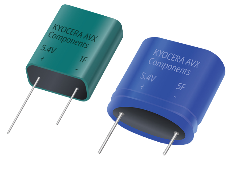
■Features ・The SCM series achieves high withstand voltage (5.0V to 9.0V) by internally connecting electric double layer capacitors in series and c...

Techdia Co., Ltd.
480+ people viewing
Last viewed: 1 hour ago
This is a connected product that uses a single layer ceramic capacitor "A type" (Class IV). It facilitates the use of narrow spaces during design a...

Kyocera Corporation
440+ people viewing
Last viewed: 20 hours ago
Kyocera supplies high-performance, high-quality multilayer ceramic chip capacitors (MLCCs) made from high-purity dielectric ceramics. By making ful...
10 models listed


Techdia Co., Ltd.
440+ people viewing
Last viewed: 1 hour ago
A gap-type ceramic capacitor is a rectangular single-layer capacitor with two electrodes arranged on its surface. By mounting the electrode array s...

Shinko Shoji Co., Ltd.
850+ people viewing
Last viewed: 1 minute ago
■Features ・Compliant with automotive quality standard AEC-Q200 ・Board bending test 5mm guaranteed ・Temperature cycle test ability of over 3,000 ...
Texol Co., Ltd.
480+ people viewing
Last viewed: 1 day ago
It is used for transmission, matching, coupling, bypass circuits, etc. of frequency heating equipment, medical high frequency application equipment...
10 models listed

Taiyo Yuden Energy Device Co., Ltd.
400+ people viewing
■Features ・Equivalent series resistance (ESR) is small. ・Equivalent series inductance (ESL) is small. - Highly effective in removing noise at hig...

Taiyo Yuden Energy Device Co., Ltd.
390+ people viewing
■Features ・AEC-Q200 qualified ・A high Q value can be obtained at high frequencies for a multilayer ceramic capacitor. ・Compact size despite high...

Techdia Co., Ltd.
440+ people viewing
Binary capacitors are available in 3 to 5 electrode array options with a shared electrode on the back side. Useful for adjusting capacitance values...
Texol Co., Ltd.
410+ people viewing
Last viewed: 7 hours ago
It is used for transmission, matching, coupling, bypass circuits, etc. of frequency heating equipment, medical high frequency application equipment...
10 models listed

Techdia Co., Ltd.
430+ people viewing
Last viewed: 1 day ago
We offer a variety of high aspect ratio single-layer ceramic capacitors that are widely used in GaN transistor packages.
Texol Co., Ltd.
480+ people viewing
It is used for transmission, matching, coupling, bypass circuits, etc. of frequency heating equipment, medical high frequency application equipment...
10 models listed

Techdia Co., Ltd.
470+ people viewing
Single layer ceramic capacitor with no setback. It has excellent solder mounting properties and is suitable for coupling and bypass applications th...

Taiyo Yuden Energy Device Co., Ltd.
410+ people viewing
■Features ・Ni metal is used for the electrodes, so migration does not occur and high reliability is achieved. ・Compact size despite high rated vo...

Techdia Co., Ltd.
490+ people viewing
A double-sided setback single-layer ceramic capacitor that does not require distinction between the front and back sides. Prevents short circuits d...

Kyocera Corporation
400+ people viewing
Last viewed: 17 hours ago
Kyocera supplies high-performance, high-quality multilayer ceramic chip capacitors (MLCCs) made from high-purity dielectric ceramics. By making ful...
10 models listed


Taiyo Yuden Energy Device Co., Ltd.
510+ people viewing
Last viewed: 1 day ago
■Features ・AEC-Q200 qualified ・Equivalent series resistance (ESR) is small. ・Equivalent series inductance (ESL) is small. - Highly effective in ...

Taiyo Yuden Energy Device Co., Ltd.
380+ people viewing
Last viewed: 19 hours ago
■Features ・It is possible to improve the mounting density. - High reliability due to monolithic structure. ・Same shape, wide capacitance range. ...
Techdia Co., Ltd.
450+ people viewing
Single layer ceramic capacitor with surface setback. It has excellent image recognition and prevents short circuits caused by epoxy creeping up.

Kyocera Corporation
580+ people viewing
Last viewed: 9 hours ago
Kyocera supplies high-performance, high-quality multilayer ceramic chip capacitors (MLCCs) made from high-purity dielectric ceramics. By making ful...
10 models listed


Taiyo Yuden Energy Device Co., Ltd.
380+ people viewing
■Features - High reliability due to monolithic structure. - Same shape, wide capacitance range. - By using Ni metal for the electrodes and plating ...