All Categories
History
This section provides an overview for digital multimeters as well as their applications and principles. Also, please take a look at the list of 120 digital multimeter manufacturers and their company rankings. Here are the top-ranked digital multimeter companies as of July, 2026: 1.Traceable(R), 2.Tinsley Instrumentation Ltd, 3.AEMC(R) Instruments.
Table of Contents
Categories Related to Digital Multimeters
A digital multimeter is generally used to measure basic electrical characteristics such as DC voltage, AC voltage, DC current, and resistance. Higher-end models can measure more exotic power profiles, including those that capture complex AC-based data. For example, AC (Alternating Current) power is frequency-based. High-end digital multimeters are capable of capturing peak currents and average currents, which are stored at different positions on an AC waveform. This kind of data can be used to troubleshoot impedance issues, power factor correction problems, and much more.
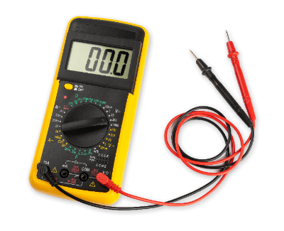
On the device, while conventional voltmeters, ammeters, and resistance meters have analog displays in which the meter pointer indicates the measured value, a digital multimeter is called a digital multimeter because it has multiple measurement functions and three- to eight-digit numerical displays. Models with extended measurement functions such as capacitance, AC frequency, and temperature are also available.
Compact and lightweight models suitable for use at construction sites are also called digital testers. The number of digits displayed is about 4 digits, and the measurement accuracy is generally 0.05 to 0.1% for DC voltage and 0.5 to 1% for AC voltage. Although the accuracy is insufficient for precise measurements in the laboratory, they are easy to use for outdoor applications. In anticipation of such use, models with a sturdy construction to withstand drops are also available.
Digital multimeters are used in a variety of situations, including measurements in laboratories, electrical adjustment of products on factory production lines, and construction and maintenance inspections of electrical facilities.
They are often incorporated into power-receiving equipment and power control panels. In such cases, in addition to basic parameters such as current, voltage, and resistance, some have built-in functions to measure capacitance, frequency, and temperature.
In addition to the specialized applications described above, inexpensive models are also available for use in general household electronic construction.
The core of a digital multimeter (DMM) consists of a high-precision, high-resolution analog-to-digital converter (A/D converter) and a processor that calculates measurement values based on digital output. The A/D converter converts the analog signal acquired by the test procedure into a digitally recognizable measurement that’s then processed by a microchip. The means of collecting the analog measurement data are described as follows.
The voltage between two probes is converted to a voltage within the dynamic range through an amplifier or attenuator that affects the voltage by either amplifying it (for low voltage) or attenuating it (for high voltage) to become the input voltage that’s transferred to the A/D converter. The processor calculates the voltage between the probes based on the digital value, amplifier gain, and attenuation factor of the attenuator, and displays the DC voltage value on the display unit.
The AC voltage is converted to DC voltage through a rectifier circuit, then input to the A/D converter, and the AC voltage value is displayed on the display unit through the same process as DC voltage.
A constant current is applied to the resistance to be measured through two probes from the constant current power supply built into the digital multimeters. The DC voltage appearing at both ends of the probes is input to the A/D converter to measure the voltage at both ends of the resistor to be measured. From this voltage value and the current value of the constant-current power supply, the processor calculates the resistance value to be measured.
To measure DC current, the voltage at both ends of the micro resistor generated by the measured current flowing through in the digital multimeters is input to an A/D converter. The processor calculates the current value from the output value of the A/D converter and displays the current value on the display unit. For AC current, the AC voltage at both ends of the micro resistor is converted to DC voltage by a rectifier circuit and input to the A/D converter.
The A/D converter of digital multimeters requires very high precision (high resolution), e.g., 24 bits or more for a 7-digit display, so a double-integral type is generally used. Therefore, the time required for conversion is relatively long, and several measurements per second is the most that can be done. However, by reducing the number of displayed digits and shortening the conversion time of the A/D converter, it is possible to shorten the measurement time.
A description of how to use digital multimeters follows
In digital multimeters, the system to be measured is connected between the two input terminals, the Hi and Lo terminals. When measuring DC voltage, connect the Hi terminal to the high voltage side and the Lo terminal to the constant voltage side, and the voltage on the Hi terminal side will be displayed based on the potential on the Lo terminal side. When measuring DC current, if the current to be measured flows in from the Hi terminal and out from the Lo terminal, the current value is displayed as positive, and in the opposite direction, it is displayed as negative. In AC voltage, current, and resistance measurements, polarity need not be taken into consideration.
For general use, the AutoRange function automatically switches to the optimum range for the voltage and current within the maximum input rating, so there is no need to search for the optimum range. However, if you need to reduce measurement time, such as when adjusting a production line, you will need to manually set the range based on the expected measurement value.
Connecting digital multimeters may affect the system under measurement and cause fluctuations in measured values. For example, if digital multimeters are connected to a circuit with very high impedance, such as when measuring the output voltage of an optical sensor in a dark environment, its internal impedance may load the measurement system, resulting in a lower value than the original output voltage.
Similarly, when measuring the current of a circuit with a small impedance, the minute resistance for voltage detection present in the digital multimeters may cause a non-negligible error in the circuit under measurement. Therefore, the influence of the digital multimeters on the circuit under measurement should be considered before deciding whether or not to use digital multimeters.
There are digital multimeters that can perform 4-terminal measurements for resistance measurement. As the term "4-terminal" implies, it consists of a pair of constant-current power supplies and a pair of voltmeters. A constant-current power supply is connected to both ends of the resistor to be measured. The voltmeter is connected to the constant-current terminals of the resistor to be measured.
The voltmeter measures the voltage at both ends of the resistor by placing a probe inside the constant-current terminals, at a point on the resistor side. The resistance is calculated from this measured voltage and the constant current value. Since the contact resistance of the constant-current terminal does not affect the measured voltage and the contact resistance of the probe of the voltmeter is negligible compared to the internal resistance of the voltmeter, which is typically as high as 10-MΩ, low resistance can be accurately measured.
*Including some distributors, etc.
Sort by Features
Sort by Area

AlphaLab, Inc. is a manufacturer of industrial and scientific measurement devices founded in 1982 and based in Utah, USA. The company’s products are mainly designed for measuring static electricity, electromagnetic fields, and other electrical parameters. These include air ion counters, electrostatic voltmeters for measuring static charge voltages, and gaussmeters. The company also offers OEM, calibration, and technical support for customers with unique project parameters. Its products are mainly used by clients in the research, environmental, and engineering sectors.
Mile-X Equipment, Inc., founded in 1979 and located in Coldwater, Ohio, USA, is a manufacturer of automotive and industrial equipment. The product offerings include automotive service equipment, such as tire changers, wheel balancers, and automotive lifts, along with industrial equipment like shop presses and oil filter crushers. These products are designed to improve efficiency, productivity, and safety in automotive repair shops, industrial facilities, and manufacturing plants. The solutions find applications across various industries, including automotive repair, heavy equipment maintenance, metalworking, and manufacturing.
OMEGA Engineering Inc., founded in Norwalk, CT, in 1962 is a manufacturer of products used to measure temperature and humidity, flow and level, and pressure. The company's product portfolio includes thermocouple probes and assemblies, pressure gauges and switches, and air velocity measurement systems, wireless systems and portable optic sensors. The company serves markets including Automotive and Electric Vehicles, Renewable Energy and Energy Storage and Electronics and IT Infrastructure. The company also offers customer services that include support, custom research projects and customized services.
B&K Precision Corporation, established in 1951 and headquartered in Yorba Linda, California, stands as a manufacturer and supplier of test and measurement instruments. Its offerings span various industries and applications, including power supplies and DC electronic loads for power testing, signal generators for signal creation, component testers for evaluating electronic components, oscilloscopes for signal waveform analysis, and spectrum analyzers for frequency spectrum measurement. These solutions provide more options for electronic system design and development across education, research, engineering, production, and maintenance sectors. The company holds ISO 9001:2015 certification for its quality management.
Telednye LeCroy was established in 1964 in Chestnut Ridge, New York and is a designer and manufacturer of oscilloscopes, modular data acquisition, sensors and calibrators for testing and improving design processes. The company makes LCR meters, electronic loads, torque sensors and load cells, PCI Express, and waveform generators for these industries: military and aerospace, consumer electronics, telecommunications, semiconductor and automotive. It also provides protocol technology training, automotive and device Interoperability testing, and signal integrity academy training services.
Lang Tools, established in 1932 and based in Racine, Wisconsin, USA, is a manufacturer of soil mixing equipment. The company manufactures hand tools, including ratcheting box wrenches, rethreading tapes, and feeler gauges, as well as specialty tools designed for professional automotive technicians and industrial users. Notably, the company pioneered and holds a patent for the first ratcheting box wrench. All of its products adhere to ISO-9001 standards in manufacturing. Land Tools also offers diagnostic services for compression and cylinder leakage, diesel engines, power steering systems, and fuel injection.
Headquartered in Everett, Washington, Fluke is an American-born company operating since 1948. Fluke offers a variety of testing equipment including digital multimeters, thermal cameras, solar PV testing equipment, thermometers, oscilloscopes, leak detection devices, as well as testing-equipment related accessories. Fluke offers direct online sales.
Astronics Corporation is a manufacturer based in East Aurora, New York, specializing in electronic and mechanical systems for aerospace, defense, electronics, and semiconductor industries. Their diverse product range includes power and motion systems, connectivity and data systems, and lighting and safety systems. Astronics Corporation also offers aircraft cabin interiors such as environmental control system, fuel access door, passenger service unit, and smart tray. Their products are utilized in the development of urban air mobility vehicles, aircraft outfitting, and defense systems. They also provide services for design, tooling, integration, and installation to support global airframe manufacturers and prime OEMs.
Rohde and Shwarz, headquartered in Munich, Germany, is a technology business that creates, develops, and promotes innovative information and communication technology products for professionals. Customers all over the world rely on Rohde & Schwarz and its cutting-edge solutions in the test & measurement, secure communications, networks & cybersecurity, and broadcast & media areas. They were created in 1993 and have regional hubs in Asia and the United States.Rohde & Schwarz has invested heavily in emerging technologies such as artificial intelligence, the industrial internet of things (IIoT), 6G, cloud solutions, and quantum technology.
Teledyne LeCroy was founded in 1964 and is headquartered in Chestnut Ridge, New York, with sales, service, and development subsidiaries in the US and throughout Europe and Asia. The company serves a wide variety of industries including semiconductor & computer, consumer electronics, automotive, and telecommunications. The company’s product categories include oscilloscopes, electronic test equipment, protocol analysis solutions such as SATA and USB devices, modular data acquisition devices, and sensors and calibrators. The company provides services such as SSD testing, automotive and device interoperability testing, and technology training.
Tinsley Instrumentation Ltd established in Braintree, Essex in 1904 is a manufacturer of precision measurement equipment such as transformer testers and submarine cable equipment. Their product portfolio includes clamp meters, Transformer Test Equipment, Decade Resistance Boxes, Resistance Measurement, and Portable Bridges. The company's products are used in research and development laboratories for conducting experiments, analyzing data, and prototyping new technologies. The company has a national distribution network and a customer and technical support center.
AEMC(R) Instruments established in Dover, New Hampshire in 1976 is a manufacturer of electrical test and measurement instruments for the industrial, commercial, and utility marketplace. Their product portfolio includes transformer ratiometers, harmonic power meters, data loggers, thermal imaging cameras micro-ohmmeters, and environmental testers. The company's products are used in industries including Aerospace and Defense, Transportation, Medical Devices, and Power and Energy. They also provide training seminars, technical support, customer service, repair, and calibration.
Chroma Systems Solutions, Inc., founded in Foothill Ranch, CA, in 2001 is a manufacturer of test instruments and automated test systems. The company's product portfolio includes AC Power Sources, AC Electronic Loads, DC Power Supplies, multimeters, and DC Electronic Loads. The company serves industries such as Oil and Gas, Aerospace and Defense, Automotive and Transportation, Construction, and Power Generation. They also offer custom packaging, warehousing, and distribution services, and customer support.
Electronic Specialties, Inc., established in Genoa City, WI in 1967, is a manufacturer of handheld test equipment and computer based engine analyzers. Their product portfolio includes marine and industrial engine testing equipment, automotive test equipment, marine test equipment, digital engine analyzer, and diagnostic equipment. The company's products are used for measuring voltage, current, resistance, capacitance, and other electrical parameters in electronic circuits and electrical systems. The company also provides services including product selection, installation, preventative maintenance, troubleshooting, and repair. The company has a national distribution network and a customer support center.
SparkFun Electronics is a manufacturer of modernized and cutting-edge electronic components and tools founded in 2003 and was established in USA. The company broad selection of goods includes sensors, development boards, kits, and modules for both experts and enthusiasts. Quality is crucial at SparkFun Electronics, and they work hard to satisfy their clients. They stand out for their adherence to open-source hardware and wealth of instructional resources, which enables them to support a thriving and cooperative community of makers and innovators.
Team Solutions, Inc., established in 1989 and headquartered in Laguna Niguel, California, USA, is a manufacturer of control systems, automation systems and various measurement instruments. The company specializes in automated, PC-based test and measurement instruments, data acquisition (DAQ) systems, and process control equipment, and it is ISO 9001 certified for consistent and accurate instrumentation, data acquisition, and process control applications. Advanced control capabilities, accuracy, and easy connection with computer systems are among the features of the products. These devices are used in a variety of industries, including electronics, research and development, production, and automation.
RJM Sales was founded in 1970 and is now headquartered in Somerset, New Jersey. The company is an employee-owned manufacturer’s representative and distribution company of industrial instrumentation and controls, filtration, gas generation, and laboratory instrumentation products. The company serves a breadth of industries including food, pharmaceuticals, coil & gas, chemical, power generation, and other markets. The company’s two main product categories are Industrial Products and Laboratory Products. Industrial Products include signal conditioners, digital indicators, and moisture analysis equipment. Laboratory Products include YSI reagents, maintenance kits, and other supplies.
Electro Static Technology, Inc., established in Mechanic Falls, Maine, in 1984, is a manufacturer of Shaft Grounding Rings, used for Protecting Electric Motor Bearings. The company's product portfolio includes Split Ring Shaft Grounding Rings, Solid Ring Shaft Grounding Rings and customized Shaft Grounding Rings to address unique application requirements. The company serves industries such as Oil and Gas, Aerospace and Defense, Automotive and Transportation, Construction, and Power Generation. The company also provides services including national distribution, product selection, installation, preventative maintenance, troubleshooting, repair and customer service.
Shortridge Instruments, Inc., since 1999 has been a manufacturer and supplier of Electronic Air and Water Balance Instruments such as AirData multimeters, and HydroData Multimeters for household and commercial uses. From Scottsdale, USA Shortridge Instruments offer both domestic and international factory direct sales for clients with no outside sales agents or representatives. The company offers free services like calibration and repair for the meters, to members of NEBB or AABC unless the meter is sent in repeatedly without repair.
Based in Bayville, NY, SAE Manufacturing Specialties Corp. is an ISO-certified supplier and manufacturer of industrial equipment, chemicals, components, ordinance, electronics, and systems for industries ranging from aerospace to high tech to law enforcement. Examples of product offerings include raw materials, chemicals, and lubricants for industrial purposes to finished products such as security helmets for law enforcement, and military ordnances. SAE also provides research and development as well as technical support for other companies in similar industries.
Pepperl+Fuchs, Inc. was founded in Mannheim, Germany in 1945 developing the forerunner of the proximity switch. Pepperl+Fuchs continues to develop proximity sensors as well as other industrial sensors including ultrasonic sensors, rotary encoders, positioning systems, display and signal processing, vibration monitoring, industrial communication, and signal processing as well as related accessories and software. Explosive protection products include safety barriers, surge protection, wireless solutions, HMI systems, power supplies, electrical explosion protection equipment, level measurement, and related software.
Tempco is based in Wood Dale, Illinois and has been in business since 1972. Tempco is a manufacturer of many types of heating elements and thermocouples with design variations. Tempco is ISO 9001:2015 certified. Temco’s electric heaters and elements include band heaters, cartridge heaters, cast-in heaters, ceramic fiber heaters, coil and cable heaters, drum heaters, enclosure heaters, flexible heaters, heat trace cable, heated hose and tubing, infrared heaters, process heaters, shroud systems, strip heaters, tank heaters, and tubular heaters. Tempco also sells various application accessories and wiring accessories.
Allied Electronics Inc., founded in 1991 with headquarters in the USA, is a distributor and supplier of fuel and vehicle servicing station equipment and accessories. The company's extensive product line of over 57,000 products includes forecourt controller parts, fuel dispenser parts, air compressors, and power conditioners. The company also provides rebuilt parts by brands that include Bennett, Daktronics, FE-Petro, and Gasboy. The company's services include equipment financing, primarily serving the retail petroleum industry, including car wash and price sign manufacturers.
United Electronic Industries, founded in 1990 and headquartered in Norwood, Massachusetts, is a manufacturer and supplier of data acquisition systems and control solutions for the aerospace, energy, and defense sectors. The company's products, including cube and rack chassis, support an array of application packages like LabVIEW, MATLAB, and Simulink. Its systems are supported by a range of over 90 I/O boards. All its products are developed in the United States. The company received a Gold Tier award from BAE Systems in 2021.
Triplett Test Equipment & Tools was established in 1901 and is headquartered in Bluffton, Ohio. The company is a manufacturer and distributor of electrical test equipment and tools. Triplett's product range includes digital multimeters, oscilloscopes, power quality analyzers, and a multiple other test equipment. The company's products are used by a wide range of customers, including electricians, engineers, and technicians. The company's products are also backed by a world-class warranty and are supported by a team of experienced engineers and technicians.
Great Lakes Industrial Supply Co. (Great Lakes) is a family business originally founded in 1954, operating out of Dearborn Heights, Michigan. Great Lakes is a distributor for industrial and contracting supplies including cutting tools, mechanic tools, power tools, and safety items. Some of the types of cutting tools Great Lakes offers include drills such as jobbers and roto hammers, taps, reamers, and dies. Mechanic tools include rachets, drivers, and sockets. Power tools include offerings from companies such as Makita and Milwaukee.
Metro Hydraulic Jack Co. is a third-generation family run business in operation since 1941. MHJ is based in Newark, NJ. MHJ distributes hydraulic jack-related equipment, tools, and parts including a broad range of cylinders, motors, valves, presses, couplings, tools, hydraulic fittings, hoses, jacks, pumps, lifts, lubrication equipment, pallet stackers, scissor lifts, and workholding devices. MHJ also offers system design services as well as engineering services and extensive repair including testing, retrofitting, and overhauling.
Colonial TelTek was founded in 1972 and operates in King of Prussia, Pennsylvania. Colonial TelTek is a division of Colonial Electric Supplies. Colonial TelTek primarily serves the telecommunications and utility industries as a parts distributor and emergency service provider. Colonial TelTek is offers 8 major product lines including aerial hardware components, bridge conduit systems and conduit accessories, fiber optic cable and splice accessories, handholes and racking products, pulling products, PVC, HDPE, and fiberglass conduit, as well as tools and accessories.
Tri-State Instrument Laboratory was established in Tulsa, Oklahoma in 159. Tri-State is a distributor and provider of calibration and related services. Tri-State also manufacturers voltage dividers, motor rotation indicators, and phase sequence indicators. Calibration services include calibration of various types off multimeters, clamp meters, electrical and resistance testers, power recorders, loop, process, and temperature calibrators, infrared and contact thermometers, and analog and digital panel meters. In addition to calibration services, Tri-State specializes in meggers, process calibrators, clamp meters, thermometers, multimeters, and other products such as digital counters, ,hour meters, and hard cases.
All Electronics Hardware, which was established in 1995, is a US designer, manufacturer, and distributor of plastic hardware, tools, and accessories located in Algonquin, Illinois. The company is ISO 90001:2015 certified and RoHS-compliant. It continually supplies products to the fastener, electronics, electrical, and OEM (original equipment manufacturer) industries. These products range from circuit board supports, cable ties, and tubing to testers and wire connectors that are routinely used in computers and construction.
Sterling Sterlco was founded in 1916 and distributes under M&M Control Service, Inc. is a specialist in industrial control units. Industrial control units are in two basic varieties: steam control family and temperature control units. Steam Control units include steam traps, Y strainers, temperature control valves, hand radiator valves, boiler feed pumps, condensate pumps, and centrifugal pumps. Temperature control units include portable chillers, central chillers, and water and oil temperature control units. Additionally, Sterling also manufactures pump tanks.
Keysight Technologies, Inc. was founded in 1939 and headquartered in Santa Rosa, California. Keysight is a global developer and manufacturer of electronic design and test solutions to communications, networking, aerospace, defense, and government, automotive, energy, semiconductor, electronic, and education industries. Keysight’s communications solutions group solutions include electronic design automation software; radio frequency and microwave test solutions, hardware and virtual network test platforms and software applications, as well as optical laser source solutions. Keysight’s electronic industrial solutions group offers various design tools and verification tools. Keysight offers product support, technical support, and training and consulting services. It sells its products through direct sales force, distributors, resellers, and manufacturer's representatives.
Jewell Instruments is headquartered in Manchester, New Hampshire. The company serves industries such as aerospace, geophysical, railroad, laboratory, and data acquisition with various measuring devices and sensors. The company has five product segments: Inertial & Tilt Sensors, GEO Instruments & Sensors, Meters & Avionics, Data Acquisition Hardware, and Triplett Test Equipment Tools. Inertial & Tilt Sensors include accelerometers, inclinometers, and inertial measurement unit devices. GEO Instruments & Sensors includes economical high-precision and ultra-precision sensors. Meters & Avionics include panel meters, avionics, and solenoids.
Sperry Instruments, established in Hauppauge, New York, in 1966, is a supplier of testing and measurement equipment for the electrical marketplace. Their product portfolio includes Scanners, Circuit breaker finders and wire tracers, Non-contact and probe voltage testers, Voltage-continuity and insulation testers and Outlet Testers. Their products are used for commercial solutions, data solutions, renewable energy, and power utilities. The company has distributors in the USA and Canada, and provides nationwide customer support.
Supply Solutions was founded in the early 2000s and operates out of Stonewood, West Virginia. Supply Solutions is a wholesale distributor serving the telecommunications industry, including traditional CATV operators, independent telephone companies and FTTX providers, as well as the contractors that support these operations. Supply Solutions offers hardware including aerial hardware including sub-components and parts,, cables, conduits, fiber optics, power supplies, sealants, test equipment, drop & instillation products, FTTX equipment including optical enclosures, headend products, underground equipment, wireless equipment, poles, as well as test equipment.
HydraCheck was established in 1990 and headquartered in West Valley City, Utah. The company is a distributor of diagnostic testing and maintenance for hydraulic systems across North America. The company provides support services for end customers as well as mechanics and technicians. The company’s product lines include testing products, diagnostic kits, and safety devices. Testing products include flanges, gauges, and thermometers while kits include identification kits and test kits. The company's safety devices include goggles, models, and guides.

Changzhou Tonghui Electronic Co. Ltd. is a manufacturer of electronic testing and measurement instruments founded in 1994 and based in Changzhou, Jiangsu, China. The company produces equipment used for testing and measurement processes, and related accessories. Its products include capacitance meters, insulation testers for electrical safety compliance testing, and automatic semiconductor test systems. It also offers data loggers, power supply units, and test leads. The company's products are mainly used by clients in the microelectronics, semiconductor, and defense sectors.

Gentec Inc., based in Québec, Canada and founded in 1959, is a manufacturer of customized products in the electronics, power, and energy management sectors. Initially offering specialized electronics services and load stabilization systems for heating systems, Gentec has now evolved into laser energy measurement instruments. The company's extensive product range includes data acquisition systems, industrial battery chargers, pyroelectric joulemeters, inverters, and current sensors, all built in its ISO 9001:2015 certified facility, catering to diverse industries' specialized needs. The company distributes its products globally through Gentec Electro-Optics.

Control elettronica, established in 1985 in Lodi, Italy, is a manufacturer and supplier of low voltage electrical devices for industrial applications. The company’s product range includes earth leakage relays, digital multimeters, energy meters, alarm systems, and insulation monitoring devices. Control electronics products meet the strictest international standards, catering to various industries needs. As a private company managed by the same family, they have been a pioneer in achieving ISO 9001 certification in 1992.
SIGLENT Technologies America, Inc., is a Shenzhen, Guangdong, China-based designer and manufacturer of electronic test and measurement instruments established in 2002. The company offers digital & handheld oscilloscopes, RF & waveform generators, spectrum & vector network analyzers, digital multimeters, and DC electronic loads. These products are used for time domain analysis of RF systems, electromagnetic pre-compliance testing, and SMPS characterization techniques in the communication sector, government facilities, and electronic manufacturing. It has achieved the US UL certification and has additional establishments in Solon, Ohio, USA, and Europe.
S.A.M.A. Italia S.r.l., established in 1974 and headquartered in Viareggio, Italy, is a manufacturer of precision measuring and control instruments and calibration solutions. The product line includes an extensive range of options, such as flow meters, temperature sensors, pressure gauges, and calibration tools. These optimal-precision devices make it possible to precisely measure and regulate vital characteristics across an array of sectors, including petrochemical, manufacturing, automotive, and aerospace. The products' stability, accuracy, and longevity are essential to quality control and industry compliance in measuring and control solutions for organizations all over the world.

Established in 2006, Testo India Pvt. Ltd., a Pune, India-based subsidiary of Testo SE & Co. KGaA, is a manufacturer and supplier specializing in measuring instruments. Complying with the ISO/IEC 17025:2017 standard set by the National Accreditation Board for Testing and Calibration Laboratories (NABL), the company produces measuring instruments for temperature, humidity, pressure, and flow (bulk fluid movement). The company also offers electrical, sound level, and nanoparticle measuring devices. These products are designed for industrial applications with regard to heating, ventilation, air conditioning, and refrigeration (HVAC-R), as well as environmental monitoring technology, in sectors like food service, retail, and pharmaceuticals.

Tes Electrical Electronic Corp., founded in 1988 and based in Taipei, Taiwan, is a manufacturer of test instruments that are sold worldwide. Its products include digital earth testers, LAN cable meters, micro-ohmmeters, power analyzers, and battery capacity testers, used in various areas, including clean room inspection, measuring electrical energy waste, evaluating solar system performance, light testing, and monitoring exposure levels of noise. The company has an annual revenue of 10 million USD. It is ISO 9002 certified, and its calibration laboratory is TAF (Taiwan Accreditation Foundation) and ilac-MRA accredited.

Sanwa Electric Instrument Co., Ltd. was established in 1941, in Tokyo as a manufacturer of measuring instruments. Their product portfolio consists of Digital Multimeters, Analog Multitesters, Insulation, Earth testers, speedometers, and related instruments. Calibrators, detectors, LCR, and clamp meters are also part of the production. The equipment helps with measuring AC/DC voltages, and current, along with resistance and insulation, and for specific measuring applications. Many various industries benefit from Sanwa's products such as speedometers for the measurement of escalator emergency stop distance and detectors to test the direction of Motor rotation before connection of the power supply.

Metrel, established in 1957 and based in Horjul, Slovenia, is a manufacturer of electrical measuring instruments and components. The company produces a wide range of products such as digital multimeters, equipment for labs, and single functional testers and supplies to customers in six continents and 70 countries. Using the measuring and testing technology, the company manufactures testing and measuring equipment in different models. It designs and does final assembly, quality control, and calibration of components before dispatching them to building facilities, power generation sites, and medical facilities.

DITEL has been a manufacturer and supplier of Led Visualization Solutions since 1984 having its offices in Spain. The company deals in Digital Panel Instrumentation for monitoring and control of industrial processes from any sensor like dashboard indicators, PID regulators, cam switches, level sensors, large alphanumeric, graphic, and number format displays, and many other devices to facilitate communication in large service corporations such as Logistics, Hospitals, Public Administrations, Parking, Financial services, etc.

AMBICO Limited., founded in 1955 and based in Ottawa, Canada, is a manufacturer of specialized doors, frames, and windows. The company is a manufacturer of specialized doors, frames, and windows; such as recessed panel, brass clad, bronze clad, as well as stainless steel doors and door frames. It has a line of engineered door and frame products including acoustic wood, acoustic steel, bullet resistant steel, blast resistant, lead lined and oversized steel doors. The company's clientele includes the U.S. Army Corps of Engineers (USACE), the U.S. Department of Defense (DoD) and Federal Bureau of Investigation (FBI).
TECPEL CO.,LTD. was established in 1990 and is a manufacturer of test and measurement devices based in Xindian, New Taipei City, Taiwan. The company manufactures various devices such as digital thermometers, temperature humidity transmitters, digital pH meters, digital handheld multimeters, and light meters datalogger. The products are manufactured under the CE requirements standards. The company was awarded the Asia-Pacific e-Business Champions of the Year 2008 from Alibaba. The company participated in various exhibitions such as Taitronix Exhibition, The 9th Taipei International Instrument Exhibition, and The Automotive Electronics Show 2018.
KIKUSUI ELECTRONICS CORP., founded in Yokohama, Kanagawa in 1951 is a manufacturer od electronic measuring instruments, electronic loads, and safety test equipment. The company's product portfolio includes Electrical Safety Testers, EMC Testers, Harmonics and Flicker Testers, Battery/Capacitor Testers, and AC Electronic Loads. The company serves industries such as Oil and Gas, Aerospace and Defense, Automotive and Transportation, Construction, and Power Generation. The company provides services such as Product Selection Guidance, Engineering Support, and Custom Manufacturing.
HT Italia S.r.l., established in 1983 and based in Faenza, Italy, is a manufacturer of test and measurement instruments. The company designed and built MASTER HT2031 in 1992, a product performing safety testing on installations and simultaneously printing a professional report thanks to the built-in printer. From then on, it has built a product portfolio consisting of infrared cameras, environmental measurement instruments, photovoltaic testers, power quality analyzers and digital multimeters. The company has acquired the quality system certification ISO 9001, and supplies its safety testers with calibration certificates made with calibrating equipment traceable to SIT or NAMAS.
Transmille Ltd is a British manufacturer of metrology calibration equipment that was established in Kent, United Kingdom in 1997. The company’s product lineup includes calibrator references and standards, precision multimeters, standard and portable electrical testing equipment, and calibration software for automating calibration processes. It also offers consultation and technical support services, as well as legacy parts or components for portfolio items no longer in production. Transmille products are used mainly by its clients in public utilities, as well as in Britain’s defense, aerospace, and industrial manufacturing sectors.
Time Electronics Ltd., established in 1967 and located in Tonbridge, England, is a manufacturer that designs and manufactures calibration and metrology instruments. The company offers a range of precision test instruments for calibration, including decade boxes, portable voltage, and current calibrators. It also provides electrical multifunction calibrators, ATE/bench calibrators and multimeters, and electrical test equipment calibrators. It offers a compact working environment to cover multiple applications in test and measurement with its CalBench system. Moreover, the company is accredited to ISO 9001:2008. It serves various industries, including electronics, aerospace and aviation, industrial sectors, and music.
BETA UTENSILI S.P.A., established in 1932, is an Italian manufacturer and supplier of workshop tools and industrial equipment, headquartered in Sovico, Monza Brianza. The company's product range includes over 16,000 tools for professional mechanics, catering to car repairs, industrial maintenance, and more. Among their offerings are the modular workshop equipment lines of Racing System (RS) C55 and Beta C45PRO, which include workbenches, modules, and more. They also provide various tools such as measuring and marking tools, cutting and general maintenance tools, plumbing tools, and power tools. These tools and equipment find applications in diverse industries, including automotive, aerospace, and mechanical engineering.

ENTES Elektronik, established in 1980 and headquartered in Istanbul, Turkey with additional offices in Germany, Greece, and India, is a manufacturer of power and energy management solutions used in industrial applications. The company’s production line is categorized into power quality and energy, electrical measurement, power factor correction, energy management hardware and software, and current transformers. It also offers protection & control products such as phase failure relays, liquid level controllers, overcurrent monitoring relays, daylight switches, and control & isolating transformers.
Founded in 1940, Kyoritsu has an 80 year history as a customer-focused organization specializing in multimeters. Kyoritsu provides analog multimeters as well as digital multimeters with and without clamps offering many varieties of measurement.
Testboy GmbH, established in Vechta, Niedersachsen in 1953, is a manufacturer of robust and professional measurement and testing devices. Their product portfolio includes Continuity Tester, Magnetic Field Tester, Two-pole Voltage Tester, Digital Multimeter and Current Measurement Clamps. The company's products are used for prototyping new technologies and measurements that are essential for quality control, research, and safety assurance. In 2000 the company's name became Testboy GmbH, from Ludwig Mers GmbH & Co.
Monacor International GmbH & Co. KG. established in Bremen, Germany in 1965, is a manufacturer of PA technology, used in various industries to provide amplified audio and communication to a large audience. Their product portfolio includes amplifiers,100-volt or active loudspeakers, Mixers and players. They also provide services including technical project management, customer service, marketing service, and product quality management. In 1980 the company opened their first branch abroad and now operates in 40 countries.
OWON Technology Inc. established in Zhangzhou, China in 1990 is a manufacturer of mini color LCD, test and measurement equipment, and home energy management systems. Their product portfolio includes waveform generators, digital multimeters, power supplies, spectrum analyzers, and thermal imagers. The company's products are used for circuit testing, voltage measurements, real-time data visualization, frequency analysis, and component testing. The company operates in Asia, North America, Europe, South America, Oceania, and Africa.
RIGOL, established in 1998, has its R&D headquarters in China and is a manufacturer of electronic test equipment with over 400 employees serving more than 60 countries and regions worldwide. The company's main products include digital and mixed-signal oscilloscopes, spectrum analyzers, RF signal generators, waveform generators, sensitive measurement products, and data acquisition systems. RIGOL's products are used for IoT, EMC pre-compliance solutions, spectrum monitoring, RF device characterization, and complex demodulation by commercial and industrial clients.

Metra Blansko s.r.o.. established in 1911 and based in Blansko, Czech Republic, is a manufacturer of electrical measurement devices. The company offers various products, including multimeters, converters, and clamp meters. Its also produces switchboard cabinets, electrical and mechanical calibration, and rail transport electrical components which are designed in compliance with ISO 9001 quality standards and offer precise and consistent performance. The company's devices are used in industries, including energy, manufacturing, and research fields.
DI-LOG TEST EQUIPMENT. established in Trafford Park, England in 1998 is a manufacturer of Test & Measurement equipment with a range of Digital Multi Meters, Clamp Meters, Environmental and Renewable. Their product portfolio includes Di-Log Test Equipment, Multifunction Testers, PAT Testers, Voltage Detectors, and Voltage & Continuity Testers. Their products are used for quality control, research and development, and troubleshooting purposes. The company provides 2 year warranty, customer support, and technical support.
Ketai Instrument (Kunshan) Co., Ltd., established in 1994 and based in Kunshan, China, is a manufacturer of measurement and testing instruments. The company has presence in more than 40 countries and its product portfolio includes analog and digital multimeters, wood moisture meters, and video monitoring testing equipment, among others. It is ISO 9001 certified for rigorous quality standards, and the products offer precision and durability, serving various industries such as electronics, woodworking, environmental monitoring, and video surveillance.

Dhanbad Lab Instruments India Pvt Ltd. (DLI) is an Indian supplier and manufacturer of laboratory and scientific instrumentation that was founded in 2012. Based in Dhanbad, Jharkhand, the company produces various microscope models, as well as spectrophotometers, ovens, incubators, and balances. They also offer after-sale support services to customers needing additional support, including installation, calibration, and maintenance. DLI products primarily supply India's educational institutions, as well as clients in the healthcare and research sectors.
Promax Test & Measurement SLU, founded in 1963 and based in Barcelona, Spain, is a manufacturer of telecommunication instrumentation and electronics equipment. The ISO 9001-certified company stocks products like digital modulators for broadcast, earth resistance meters, and optical fiber fusion splicers used to provide testing solutions for satellite, cable, and digital terrestrial television. It stocks over 200 products at its Barcelona facility, with 18 calibration centers and several service centers worldwide. It produces on-demand PCB circuit boards and electronic equipment and offers software development, training, and industrial design services.
OWON - Fujian Lilliput Optoelectronics Technology Co., Ltd is based in China since 1990 as a manufacturer and supplier of test and measurement equipment. The company produces Digital Oscilloscopes available as handheld, virtual, tablet, and benchtop types as well as probes. They have Single Channel and Dual Channel Waveform Generators, along with Digital Multimeters and Programmable DC series Power Suppliers. There are also different types of Thermal Imagers, Spectrum Analyzers, and Anenmo Meters that can provide more than one kind of measurement.
GW Instek or Good Will Instruments is a Taiwanese instrument maker founded in 1975. GW Instek has over 300 product lines, which include Oscilloscopes, Spectrum Analyzers, Signal Sources, Basic Tests and Measurement Instruments, Safety Monitoring Systems, and more. Leading manufacturers choose them as their test and measurement provider. GW Instek has become the leading brand in the electronic test and measurement industry. They help electronic industries reduce testing costs and increase competitiveness. GW Instek has subsidiaries in five countries and is sold to more than 80. Their mission is to reduce total costs and create customers value from cost savings.
SIGLENT Technologies was established in 2002 and is headquartered in Shenzhen, China, and specializes in the design, manufacturing, and supplying of electronic measurement instruments. The company develops oscilloscopes, waveform generators, spectrum analyzers, digital multimeters, and other essential testing equipment. These instruments have various applications and are used by engineers, researchers, educators, and technicians. Their clientele includes research institutions, educational institutions, electronics manufacturers, and service providers. The company also provides solutions to Automotive electronics usually for testing equipment and to Intelligent Manufacturing where it helps with EMI debugging and even IoT industries benefit with aid in the verification of devices.
Yokogawa Test & Measurement Corporation was founded in Japan in 1954. Yokogawa currently serves a wide array of industries including the aerospace, automotive, consumer electronics, semiconductor and telecommunications industries with both hardware and software solutions. Among Yokogawa’s suite of products are oscilloscopes, voltage probes, power analyzers and meters, data acquisition tools, optical test equipment, a wide variety of handled meters, calibrators, and testers; analog instruments, and manometers.
Socomec is based in Gurgaon, Haryana, India, and is a manufacturer of power safety and control products that was established in 2007 as a subsidiary of the Socomec Group. The company’s product lineup includes uninterruptible power supply (UPS) systems for protecting important electronic installations, power meters for monitoring applications, and automatic as well as manual transfer switches for managing or protecting the supply of power. The company is ISO 14001 and ISO 45001-certified, and mainly serves clients in the commercial and industrial sectors.
Milwaukee Electric Tool Corporation, established in 1924 and headquartered in Brookfield, Wisconsin, is a manufacturer and marketer of heavy-duty, portable electric power tools and accessories for professional users. The company offers a wide range of products including cordless power tools, outdoor tools, hand tools, PPE, workwear, and more. It also offers a range of personal protective equipment including safety glasses, gloves, and respirators. Its product allows users to transfer tools and equipment from the crib to the job site and from one job site to another. It serves several industries, including construction, plumbing, electrical, carpentry, and welding.
Hoyt Electrical Instrument Works Inc., established in 1904, is a manufacturer of analog and digital panel meters, transformers, shunts, switches, and personal safety devices, located in Penacook, New Hampshire, the United States. The company’s products are designed to meet and exceed industry standards. It offers a wide range of test and measurement instruments, making its a comprehensive solution for customers’ needs. It is not only an analog panel manufacturer, but also has evolved to provide value-added custom solutions that keep the world spinning in the right direction.
UNI-TREND TECHNOLOGY CO., LTD. was established in 1988 and is a manufacturers of measuring and imaging devices based in Dongguan, Guangdong, China. The company produces various products such as digital multimeters, electrical power testers, DC electronic loads, handheld thermal cameras, and thermal imaging monoculars. The products are used in various applications such as industry electricity, environment monitoring, communication, photovoltaic power station, and ranging and mapping. The company has obtained ISO 9001 and ISO 14001 certifications.
CATU, formed in 1919 and based in Bagneux, France, is a manufacturer of safety solutions and equipment against electrical risks for transportation and distribution networks of electrical energy. The company crafts protection kits for electrical intervention, insulating blankets, locking padlocks, and regulatory posters and flags. It also produces maneuvering and rescue sticks, installation controllers and measuring devices, as well as jumper clamps and accessories. Its insulating blankets have acid resistance, oil resistance, and ozone resistance properties. It has passed the ISO 9001 and ISO 14001 certifications.
Benning, founded in 1938 and based in Germany, is a developer and manufacturer of OEM power supplies, electrical machines, testing measuring, and safety equipment. These products include UPS systems, traction motors, charging stations, appliance testers, and digital multimeters. The products offered by the company are used in the medical, power, distribution, water treatment, mining, and telecommunication sectors. The company also runs service centers for electrical machines to perform system checks, preventative maintenance, and calibration processing.
FLIR Systems, established in 1978 and headquartered in Wilsonville, Oregon, is a manufacturer of thermal imaging cameras and sensors. Its product range includes thermal cameras and sensors for security, robotics, and more. The company offers unmanned aerial vehicles (UAVs) with thermal capabilities for search and rescue, along with software solutions for image processing, along with services such as training and maintenance complement their offerings. Its products are utilized in security, robotics, autonomous vehicles, medical devices, and firefighting, serving diverse industries.
Beha-Amprobe, founded in 1948 and based in Glottertal, Germany, is a manufacturer of testing tools used in industrial, commercial, and residential applications. The company stocks several tools, including digital multimeters, appliance testers, and voltage detectors. In 1981, it opened its first production site in Ireland, and later, in 1986, it launched the second factory in the same country. In 1992, the company introduced the first installation tester with an integrated printer, which was used to certify facilities and electrical devices. In 1996, it opened a new production site in China to increase the production of electrical testing instruments and components.
CENTER TECHNOLOGY CORP., founded in 1998 and headquartered in New Taipei City, Taiwan, is a manufacturer of handheld test instruments distributed worldwide. Its diverse product line includes Clamp Meters for current measurement, Gas Detectors to detect gases, Sound Level Meters for sound pressure measurement, Light Meters to gauge light intensity, and Thermometers for temperature measurement. Its adherence to producing quality test instruments has solidified its name globally in the field.
USAG, founded in 1926 and headquartered in Vimercate, Lombardy, Italy, is a renowned manufacturer of professional tools. The company offers a wide range of products, including sockets, wrenches, torque bars, pneumatic tools, and griffes, which find extensive use across automotive, industrial, and mechanical applications. In 1991, the company became part of the French Group Facom Tools S.A., subsequently joining The Stanley Works and, by March 2010, becoming a part of the Multi-National Group Stanley Black & Decker Inc.
TEKTRONIX, INC., founded in 1946, is a manufacturer of measurement solutions used in 3D sensing, EMI/ EMC testing, high-speed serial communication, material science engineering, and Wireless & RF testing. The products include oscilloscopes & probes, signal generators, margin testers, multimeters, and analyzers. The company's products are used in advanced research, aerospace & defense, automotive, power semiconductor, and medical industries. The Bracknell Berkshire company offers calibration, repair, asset management, package assembling, and testing services following NEMA, HAlT & HASS, environmental, and shock-vibration testing.
Greenlee, founded in Rockford, Illinois, in 1862 is a manufacturer of Electrical Tools and Telecommunications Tools. The company's product portfolio includes Plumbing Tools, Utility Tools, Power Tools and Accessories, and Wire and Cable Electrical Test and Measurement equipment. The company serves markets including Automotive and Electric Vehicles, Renewable Energy and Energy Storage and Electronics and IT Infrastructure. They also provide services such as Product Selection Guidance, Engineering Support, and Custom Manufacturing.
Milwaukee Tool, established in 1924 and headquartered in Brookfield, Wisconsin, USA, is a manufacturer of heavy-duty power tools, hand tools, and accessories The company offers a wide array of accessories, such as bits, blades, and sockets, to complement their cordless and corded power tools, including hammer drills, saws, and wrenches. Milwaukee Tool's products are utilized by construction workers, mechanics, electricians, and contractors for various tasks, including drilling, sawing, fastening, vehicle repairs, electrical installations, and construction projects.
Amprobe, founded in Everett, WA, in 1948 is a manufacturer of Ultrasonic Leak Detectors. The company's product portfolio includes battery testers, Electrical and HVAC Test and Measurement Tools, Digital Multimeters, Clamp Meters, and Wire Tracers & Cable Locators. The company serves industries such as Oil and Gas, Aerospace and Defense, Automotive and Transportation, Construction, and Power Generation. They also provide services including product selection, installation, preventative maintenance, troubleshooting, and repair.
Chauvin Arnoux began in 1893 in France and took off in 1905 with the invention of the magneto ohmmeter. Chauvin Arnoux is an integrated manufacturer of portable test and measurement instruments used in the electrical sector, education, laboratories, and maintenance. A sample of Chauvin Arnoux’s products include calibrators, electrochemical measurements, relays, analystical software, and accessories. Chauvin Arnoux also offers industrial subcontracting, leveraging its large network of independently operating yet functionally integrated subcontractors’ abilities to manufacture and install PCBs, specialty items, sheet metal, tooling, and more.
RYOBI was established in 1943 and is a manufacturer of builders' hardwares based in Fuchu, Hiroshima, Japan. The company sells various products such as air compressors, garden shredders, glue guns, pest control, and rotary hammers. The products are branded into different categories based on platforms such as 18V One+, 40V, 80V, USB Lithium, and Link Storage. The company is affiliated with The Home Depot as the exclusive seller and distributor of the products. The company also marketed the DIY product line under the brand of Ryobi Nation.
ADC Corporation, founded as a subsidiary of Takeda Riken Industry Co., Ltd in 1971 and based in Saitama, Japan, is a producer of analog measurement devices like optical power meters, source monitor units, and digital multimeters. Separating from Takeda Riken Industry Co., Ltd (Present Adventest Corporation) in 2003, the company began being a developer, manufacturer, and distributor of optical and electronic measuring instruments, digital multimeters, monitors for DC voltage/current sources and digital electrometers which they specialize in.
SENECA srl, established in 1986 and based in Via Austria, Italy, is a manufacturer and supplier of automation interfaces. Its product portfolio includes data acquisition, automation systems, industrial communications, remote control, power monitoring, and electrical measurement. They are used in multiple industries which include steel, water treatment, automotive, oil, gas, chemical, metal, and pharmaceutical. The company also offers automation solutions ranging from single components to the implementation of turnkey systems.
Gossen Metrawatt GmbH, founded in 1906 as Guggenheimer AG and currently a subsidiary of GMC Instruments Group, is a manufacturer and supplier based in Nürnberg, Germany, developing measuring technology systems. The company’s measuring and test technology is designed for electric safety in systems, devices, and machines. This technology is also applicable in areas such as e-mobility and medical engineering. It also offers battery testing technology, multimeters, calibrators, and power supply technology. Its product range further includes technology developed by other companies, such as Camille Bauer Metrawatt AG, including indicator instruments and transducers.
Established in 1992, Fanox is a famous manufacturer and supplier of safe and dependable protection relays headquartered in Pais Vasco, Spain. The company's concept is centered around research and innovation, with a significant allocation of resources towards design engineering. One of the intentions of the energy transition in the power business is to promote and integrate Renewable Energies. This phenomenon results in the developing of a more adaptable and distributed electrical infrastructure, necessitating a digital transformation of the business to manage it effectively.
Tense Elektronik is a manufacturer and supplier of electronic products and technologies in industrial automation solutions established in Turkey since 2006. The company specializes in automatic control sensors, controllers, energy analyzers, multimeters, frequency meters, ammeters, timers, among others. It serves industrial sectors such as automotive, manufacturing, construction, food and aerospace. The company's products improve operational efficiency, fluid processes in industries and the optimization of production lines and quality control processes. The company has certification in the Iso 9001:2015 Quality Management System, TSE Certificate and RoHS.
TENMARS ELECTRONICS CO., LTD., established in 1991 and based in Taipei, Taiwan, is an ISO-9001-certified manufacturer and supplier of test and measurement instruments. The company's product range includes test and measurement devices, wireless network tools, environmental monitoring equipment, health and safety devices, HVAC tools, and electrical and maintenance instruments. These products assist professionals in diverse analytical and testing tasks. Industries served include electronics, telecommunications, environmental management, healthcare, and HVAC. The company is used in the design, production, and distribution of user-friendly and quality instruments.
Iconic Engineering Limited (IEL) is a supplier and distributor of electrical maintenance and analysis equipment. Based in Dhaka, Bangladesh, the company stocks various products for electrical testing, measurement or maintenance, including digital multimeters, clamp meters, insulation testers, and thermal scanners. These are utilized by client manufacturers as well as companies in the power generation and distribution, solar energy, HVAC, and automotive sectors. IEL also offers additional support services for customer projects, such as environmental impact assessment and calibration of electrical instruments.
PCE Instruments UK Ltd., started in 199 and headquartered in Manchester, UK, is a manufacturer and supplier of test instruments, equipment, and tools for weighing, measuring, and control systems. The company offers more than 500 test equipment, including analyzers, inspection cameras, meters, detectors, and sensors, with applications in various fields like data acquisition, electrical engineering, environmental science, building inspection, and food processing. Its manufacturing and development division is ISO 9001 certified, all its test instruments, equipment, and tools are factory calibrated, and the company also provides services for custom test instrument design, installation, and maintenance.

Fluke Calibration, established in 1948, headquartered in Everett, Washington, is a manufacturer, distributor, and supplier of precision calibration equipment and software. Their products include temperature calibrators, electrical calibrators, and pressure calibrators, serving industries such as aerospace, automotive, manufacturing, and pharmaceuticals. Their calibration solutions ensure accurate measurements, compliance with industry standards, and traceability. Their products are used to calibrate and maintain the accuracy of instruments, making them essential tools for industries that require precise measurements and consistent performance.
SEFRAM INSTRUMENTS SAS, founded in 1947 and headquartered in St Etienne, France, operates as a manufacturer and supplier of electronic equipment for data acquisition and TV meters. Its product range comprises recorders & dataloggers, TV meters & RF test instruments, power supplies, as well as electronic loads, and signal generators, applied in various recording-related fields. The company holds ISO 9001 certification, signifying its adherance to maintaining quality in product manufacturing.
PeakTech Prüf- und Messtechnik GmbH, established in 1957 and based in Ahrensburg, Germany, is a manufacturer and supplier of electronic measurement technology. The company's product portfolio includes multimeters, voltage testers, thermal imaging cameras, isolating transformers, and sound level meters, as well as calibrators. These products are applied in various industries, including electrical engineering, environmental monitoring, aviation, telecommunications, and research and development. The company provides customer services, including technical support, repair, service requests, and product development.
Aim and Thurlby Thandar Instruments, founded in 1989 and based in Huntingdon, UK, is a manufacturer of electronic test and measurement equipment and laboratory supplies. Its products include EMC analyzers, waveform amplifiers, pulse generators, multimeters, and DC power supplies. It also provides accessories related to the products, including power adaptors, cases, rack mounts, cables, and connectors. The company complies with the WEEE directive, and all its products are listed in Annex I of the RoHS directive. It sells its products worldwide through various distributors, and all the products are designed and manufactured at the Huntingdon facility.
Pyle Audio, established in Brooklyn, New York in 1960, is a manufacturer of car audio systems, and stereo systems. Their product portfolio includes speakers, vehicle subwoofers, DJ controllers, Audi processers, and microphone systems, as well as modern media systems on wheels, including navigation systems, DVD players, and iPod interfaces. The company has 5 brands and around 1000 products. They work with nationwide distributors and partners and provide customer service and customized services.
Accele Electronics, Inc. is based in Santa Fe Springs, California. Accele has a 30 year history as a manufacturer and distributor of automotive technology solutions, also offering services such as, installation and support throughout its 30+ year history. Example products include LCD monitors, headrest monitors, mirror monitors, drive and park sensors, video recording and camera kits and accessories, A/V switchers, RV camera systems, cables, lighting, HUD, security systems, fuses and circuits, relays, bus and coach amenities, as well as comfort and convenience items.
Klein Tools is a fifth-generation family-run producer of hand tools founded in 187 and headquartered in Lincolnshire, Illinois. Klein Tools sells worldwide directly and through distributors. Klein Tools has a family of companies under its brand including Alco, Civitella, Mumme Tools, Tulmex, and Wattmaster. Klein Tools serves several industries including construction, HVAC/R, plumbing, telecom, municipal, and industrial. Some of the tools Klein Tools produces include non-contact voltage tester bens, multi-bit screwdrivers, digital circuit breaker finders, advanced circuit tracer kits, and multi-bit electronics screwdrivers.
Adolf Würth GmbH & Co. KG, established in 1945 and headquartered in Künzelsau, Germany, is a supplier and distributor of fasteners and screws. The company's product portfolio includes building supplies, fittings, tools, machinery, and automotive parts. These products are utilized in various industries, including construction, manufacturing, automotive, metalworking, and agriculture and horticulture. The company offers services that encompass technical support, delivery, training, customized solutions, and product catalogs. The company is certified for quality management with ISO 9001 and ISO 14001 certifications.
Hoffmann SE is a supplier and distributor of quality tools, workshop equipment, and personal protective equipment that was established in 1919 and is based in Munich, Germany. The company’s product portfolio includes hand tools, power tools, measuring tools, clamping tools, cutting tools. The performance, excellence, and dependability of the tools, workshop equipment, and personal protective equipment have been carefully considered. The products are utilized in various industries, including metalworking, automotive, aerospace, jewelry, and electronics. Additionally, it is designed with energy efficiency and environmental compliance in mind.
TEXIO TECHNOLOGY CORPORATION has been in operation in Japan for over 60 years. TEXIO specializes in custom orders of a variety of different products including power supplies. TEXIO also specializes in DC power supplies, oscilloscopes, multimeters, function generators, and safety testers.
Hioki E.E. Corporation was founded in 1935 and headquartered in Ueda, Nagano. Hioki provides testing & analysis, manufacturing & inspection, and equipment maintenance to industries including mobility, battery, motor, energy, electronic components, and infrastructure. Hioki’s has 10 primary product categories which are: recorders and data loggers including oscilloscopes, LCR/Resistance Meters, safety testing including signal generators and calibrators, power meters including power quality analyzers, probes & sensors, optical & PV maintenance & telecommunication, environmental measuring, DMM & testers & field measuring, IoT & new solutions & meter relay, and bare board & package testing.
Computer Network Accessories Inc., based in Dayton, Ohio, is an online supplier of several electronic products, such as power adapters, network hardware, and bulk cabling. The company also stocks computer hardware and accessories like keyboards, hard drives, and modems and sells toner cartridges compatible with several brands like HP, IBM, and Epson. The company has an online catalog of its products where customers can make orders, and it allows purchase orders. It provides free shipping for all orders over $99, and customers can return goods if unsatisfied within 30 days of purchase.
Shanghai Yihua V&A Instrument Co Ltd., established in Hong Kong in 1970, is a B2B platform that supplies trade shows, online marketplaces, magazines, and sourcing apps. Their product portfolio includes e-commerce conferences, China sourcing directories, Online supplier directories, e-Magazines, and trade shows. Their products help suppliers and buyers to get market insight and market data. The company has 10 million registered buyers and users worldwide. In 1995 the company launched Asia's first international trade website, Asian Sources Online and in 2000 they were listed on NASDAQ.
Sifam Tinsley UK is based in London, England, United Kingdom, and is a supplier of electrical control and monitoring products for industrial automation that was established in 1946 as a subsidiary of Sifam Tinsley Instrumentation. The company’s product inventory includes digital and analog panel meters for measuring AC and DC voltages or currents, power quality analyzers for gauging parameters such as harmonics or flicker, and transducers for converting electrical signals into digital or analog inputs. The company’s products are commonly used by clients in Europe’s marine, power generation, and mining industries.
Solar Biz Inc. began in the 1970s in Ft. Atkinson, Wisconson. Solar Biz offers complete solar panel systems for residential and commercial customers ranging from under 5 watts to over 400 watts. Systems include solar panel components with racking and mounting, inverters, power centers, solar charge controllers, batteries, and accessories, AC and DC enclosures, circuit protection, hydro and wind generators and accessories, water pumps and water filtering, tanks, heaters, hot tubs, rain catchments, and appliances such as fans, gas ranges, refrigerators and freezers.
Ranking as of July 2026
Derivation Method| Rank | Company | Click Share |
|---|---|---|
| 1 | Traceable(R) |
2.3%
|
| 2 | AEMC(R) Instruments |
1.9%
|
| 3 | Tinsley Instrumentation Ltd |
1.9%
|
| 4 | Electronic Specialties, Inc. |
1.8%
|
| 5 | Astronics Corporation. |
1.7%
|
| 6 | Ross Engineering Corp. |
1.7%
|
| 7 | Rohde & Schwarz USA, Inc. |
1.7%
|
| 8 | RJM Sales, Inc. |
1.7%
|
| 9 | AlphaLab, Inc |
1.6%
|
| 10 | Chroma Systems Solutions, Inc. |
1.6%
|
Derivation Method
The ranking is calculated based on the click share within the digital multimeter page as of July 2026. Click share is defined as the total number of clicks for all companies during the period divided by the number of clicks for each company.Number of Employees
Newly Established Company
Company with a History
*Including some distributors, etc.
*Including some distributors, etc.
| Country | Number of Companies | Share (%) |
|---|---|---|
|
United States of America
|
37 | 39.8% |
|
Japan
|
13 | 14.0% |
|
China
|
8 | 8.6% |
|
Germany
|
7 | 7.5% |
|
United Kingdom
|
6 | 6.5% |
|
Italy
|
5 | 5.4% |
|
Taiwan
|
4 | 4.3% |
|
Spain
|
3 | 3.2% |
|
Turkey
|
3 | 3.2% |
|
Canada
|
2 | 2.2% |
|
Slovenia
|
1 | 1.1% |
|
Czech Republic
|
1 | 1.1% |
|
India
|
1 | 1.1% |
| Pakistan | 1 | 1.1% |
|
Netherlands
|
1 | 1.1% |
169 products found
169 products

Engineer
840+ people viewing
■ Features ・ Compact digital multimeter with various measurement items. ・ A gold plating test lead that does not cause poor contact. ・ With auto -p...

TEXIO TECHNOLOGY CORPORATION
490+ people viewing
Last viewed: 14 hours ago

Custom Co., Ltd.
1300+ people viewing
It is a digital type characteristic that is excellent in accurate measurement and corresponds to various measurement items. ■ Standard models that...

Fluke Calibration
470+ people viewing
■Multi-functional multimeter. For manufacturing, development, service, etc. ・5.5 digit resolution ・Basic DC voltage accuracy 0.015% ・Dual displa...

TEXIO TECHNOLOGY CORPORATION
950+ people viewing
Last viewed: 51 seconds ago
■Dual measurement display makes measurement more efficient and speedy The GDM-8351 features high precision DC voltage accuracy (0.012%), dual measu...

IGOL TECHNOLOGIES, INC.
610+ people viewing
Last viewed: 4 hours ago
■Product features ・Resolution: 2,200,000 counts (DM3068), 240,000 counts (DM3058, DM3058E) ・Voltage accuracy: 0.0035% DC (DM3068), 0.015% DC (DM3...
3 models listed

A-Gas Japan Co., Ltd.
840+ people viewing
Last viewed: 2 hours ago
■Features ・DC voltage: ~1,000V ・AC voltage: ~1,000V ・DC current: ~10A ・AC current: ~10A ・Resistance: ~60MΩ ・Frequency: ~1KHz ・Capacitance: ~...

TEXIO TECHNOLOGY CORPORATION
560+ people viewing
Last viewed: 1 day ago
■6 1/2 digit digital multimeter with high visibility thanks to the VFD (fluorescent display tube) 3-color display and multi-point measurement possi...

Teledyne LeCroy
490+ people viewing
■ Characteristics ・ 4.3 inch LCD display ・ Equipped with histogram/trend function
2 models listed

PERITEC INC.
640+ people viewing
■All-in-one measuring device This is a measuring instrument that contains five common measuring instruments in one box. Saves space and increases w...

Fluke Calibration
370+ people viewing
Last viewed: 1 day ago
The 8588A Reference Multimeter is the world's most stable digital multimeter. Designed for calibration laboratories, this long precision reference ...

Custom Co., Ltd.
1680+ people viewing
Last viewed: 14 hours ago
It is a digital type characteristic that is excellent in accurate measurement and corresponds to various measurement items. ■ A multifunctional ty...
TEXIO TECHNOLOGY CORPORATION
550+ people viewing
■6 1/2 digit digital multimeter with high visibility thanks to the VFD (fluorescent display tube) 3-color display and multi-point measurement possi...

Japan INSDAC Co., Ltd.
990+ people viewing
■Features ・4 1/2 digit LCD display with backlight ・ACV/DCV, ACA/DCA, R, C, Hz, hFE, diode test, continuity buzzer test ・High resolution of 10μV,...

Fluke Calibration
520+ people viewing
Last viewed: 1 day ago
The 8558A 8.5-digit multimeter provides 5 megasamples/second high-resolution digitization for system automation in laboratory and manufacturing ins...
TEXIO TECHNOLOGY CORPORATION
440+ people viewing
■6 1/2 digit digital multimeter with high visibility thanks to the VFD (fluorescent display tube) 3-color display and multi-point measurement possi...

Drapas Co., Ltd.
750+ people viewing
Last viewed: 10 hours ago
■Summary You can learn the basics of circuit meters while assembling. We also have a wide range of specialized texts that match the curriculum. Ide...

TEXIO TECHNOLOGY CORPORATION
400+ people viewing
■Dual display DMM with thermocouple miniature plug The DL-1060 series is a high resolution, 6 1/2 digit digital multimeter with 1,199,999 counts. T...
TEXIO TECHNOLOGY CORPORATION
450+ people viewing
Last viewed: 14 hours ago
■Dual display DMM with thermocouple miniature plug The DL-1060 series is a high resolution, 6 1/2 digit digital multimeter with 1,199,999 counts. T...

Japan INSDAC Co., Ltd.
440+ people viewing
■Features - Can measure and display AC circuit electrical parameters such as current, voltage frequency, power (active power, reactive power, appar...
TEXIO TECHNOLOGY CORPORATION
540+ people viewing
Last viewed: 1 hour ago
■Dual display DMM with thermocouple miniature plug The DL-1060 series is a high resolution, 6 1/2 digit digital multimeter with 1,199,999 counts. T...

TEXIO TECHNOLOGY CORPORATION
990+ people viewing
Last viewed: 9 hours ago
■High-performance digital multimeter with easy-to-read graphical displays such as large-screen trend charts and a 100,000-point data log The GDM-90...

Japan INSDAC Co., Ltd.
570+ people viewing
Last viewed: 1 day ago
■Features ・BLE 4.0 wireless transmission, more stable, lower power consumption (MU18B only) ・Graph and diagram modes help analyze data trends ・3...
TEXIO TECHNOLOGY CORPORATION
510+ people viewing
Last viewed: 11 hours ago
■High-performance digital multimeter with easy-to-read graphical displays such as large-screen trend charts and a 100,000-point data log The GDM-90...

Custom Co., Ltd.
930+ people viewing
Last viewed: 19 hours ago
■ Thin, palm -sized digital multimeter. ・ Comes with a convenient storage case for mobile phones. -The measurement functions have each function of...

T&M Corporation Co., Ltd.
610+ people viewing
Overview ■Shockproof case The multimeter's exterior is a shockproof case that protects it from bumps and drops. It also has a test lead holder on t...

Japan INSDAC Co., Ltd.
690+ people viewing
Last viewed: 18 hours ago
■Features ・BLE 4.0 wireless transmission, more stable, lower power consumption (MU16B only) ・Graph and diagram modes help analyze data trends ・3...

A and Day Co., Ltd.
1560+ people viewing
Last viewed: 12 hours ago
9 functions including voltage, current, resistance, capacitor, frequency, diode check, continuity check, duty cycle measurement and non-contact vol...
4 models listed


Rigor Japan Co., Ltd.
380+ people viewing
Last viewed: 1 day ago
■Summary The DM3068 series digital multimeter has 6.5 digits of accuracy. Designed for high-accuracy, versatile, and automated measurement test req...

A-Gas Japan Co., Ltd.
520+ people viewing
Last viewed: 2 hours ago
■Features ・DC voltage: ~1000V ・AC voltage: ~1000V ・DC current: ~10A ・AC current: ~10A ・Resistance: ~60MΩ ・Frequency: ~1KHz ・Capacitance: ~60...
2 models listed
