All Categories
History
This section provides an overview for 555 timer ics as well as their applications and principles. Also, please take a look at the list of 8 555 timer ic manufacturers and their company rankings. Here are the top-ranked 555 timer ic companies as of August, 2026: 1.Digi-Key Corporation, 2.Cissoid, 3.STMicroelectronics.
Table of Contents
Categories Related to 555 Timer ICs
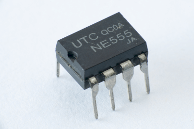 A 555 timer IC is commonly used as an oscillator in electronic circuits. It is well-suited for applications such as driving LED displays by supplying fixed-cycle pulses.
The XX555 is a popular variant of the 555 timer IC, with the 'XX' prefix varying by manufacturer. It is renowned among digital circuit designers for its reliability and versatility.
Indeed, it is one of the most iconic semiconductors in modern electronics.
555 timer ICs are widely used in oscillator circuits within digital systems, providing the main synchronization signal. These fixed-cycle signals are essential for microcontrollers and system controllers to synchronize their operations.
LED display circuits leverage the 555 timer IC for its ability to freely set display durations, making it versatile for various applications.
Furthermore, in digital circuit design, situations often arise where a signal of a fixed period and arbitrary frequency is needed. The 555 timer IC is highly advantageous in such scenarios due to its ease of use and flexibility.
The XX555 timer IC primarily comprises three circuits: a window comparator, an RS-flip-flop (RS-FF), and a charge/discharge circuit utilizing capacitors (C) and resistors (R). Its basic operation involves connecting the output of the window comparator to the RS-FF, and then to the charge/discharge circuit through an open collector transistor buffer. This setup creates a feedback loop essential for its functioning.
In the charge/discharge circuit, voltage is applied to the capacitor (C). When the capacitor's charge reaches a specific voltage, the window comparator activates. As the voltage hits a predetermined level, the comparator's output switches high, triggering the RS-FF and turning on the transistor buffer. This action initiates the discharge phase. The subsequent discharge causes the comparator's output to switch low, resetting the RS-FF and resuming the charging phase.
This cyclic operation results in the NOT(Q) output of the RS-FF inverting at a set interval. Consequently, the 555 timer IC's output (Q) also inverts to sync with NOT(Q).
*Including some distributors, etc.
Sort by Features
Sort by Area


Cissoid, founded in 2000 and headquartered in Mont-Saint-Guibert, Walloon Region, is a manufacturer of high temperature semiconductors. They deliver standard products and custom solutions for power management, power conversion and signal conditioning in extreme temperature and harsh environments. Their solutions range from system-on-chip to complete SiC and GaN based inverter platforms to support an ever-growing range of e-mobility and high-power applications. The company has been supplying products to leaders in the Oil & Gas, aeronautic, Industrial and automotive markets.
ST Micro Electronics is a global semiconductor company serving customers with innovations to have a positive impact on people's lives. Their product line is micro electronic systems, such as switches, controllers, sensors and drivers. The main selling point of ST Micro Electronics is its provision of sustainable products, and introducing their electronics to create a more sustainable world. The company, as well as providing the electronic devices, also provides software and support, ensuring that all fields are covered to provide a fully provide a supported and strong relationship with their customer base. ST Micro Electronics believe that technology plays a key role in helping to solve environmental and social challenges, which is why their semiconductor technologies start with their employees, their customers and partners.
ABLIC, Inc. is a manufacturer of analog semiconductors and integrated circuits (ICs) based in Minato-ku, Tokyo. Originally established in 2016, the company is a subsidiary of Seiko Instruments, Inc., and was renamed SII Semiconductor Corporation in 2018. The company produces memory, logic, and power management ICs, as well as various sensors for use in mobile computers, industrial equipment, wearable tech, and automotive systems. These supply clients in the consumer electronics, factory automation, and medical equipment industries.

MAKERS Co. is based in Egypt and is a supplier of electronic devices and spare parts for various industrial applications. The company's online and offline product folio consists of aluminum profiles and shafts, development boards, automotive electronic parts, batteries, and chargers in various brands such as Raspberry Pi, Arduino, and, H-Bridge, for the automotive, digital data transmission, and, electronics device manufacturing industries. The company also offers Connectors, diodes, Holders Breadboards, and, PCB Boards that are needed in electronics research institutes, the power production sector, and, gadgets development companies.
Ranking as of August 2026
Derivation Method| Rank | Company | Click Share |
|---|---|---|
| 1 | Digi-Key Corporation |
39.2%
|
| 2 | Cissoid |
17.6%
|
| 3 | STMicroelectronics |
14.9%
|
| 4 | MAKERS Co. |
9.5%
|
| 5 | Sierra IC Inc. |
8.1%
|
| 6 | BC Robotics Inc. |
4.1%
|
| 7 | ABLIC Inc. |
4.1%
|
| 8 | HobbyTronics Ltd |
2.7%
|
Derivation Method
The ranking is calculated based on the click share within the 555 timer ic page as of August 2026. Click share is defined as the total number of clicks for all companies during the period divided by the number of clicks for each company.Number of Employees
Newly Established Company
Company with a History
*Including some distributors, etc.
*Including some distributors, etc.
| Country | Number of Companies | Share (%) |
|---|---|---|
|
United States of America
|
2 | 40.0% |
|
Belgium
|
1 | 20.0% |
|
United Kingdom
|
1 | 20.0% |
| Egypt | 1 | 20.0% |
35 products found
35 products

Techno Flash Co., Ltd.
490+ people viewing
Last viewed: 7 hours ago
This is a daily timer board for USB connected devices that supports DC5V. ■Summary ・You can use it as a "timer" for the following "DC5V compatibl...

KYUSHU DENTSU COMPANY LIMITED
700+ people viewing
Last viewed: 5 hours ago
■Features 5.0×3.2mm size RTC module This RTC-3049-C2 is a product with built-in RTC function via SPI-Bus connection and a temperature-compensated ...

Nisshinbo Micro Devices Inc.
990+ people viewing
Last viewed: 1 day ago
■Summary R3121 is a voltage detector with a maximum input of 36V (absolute maximum rating: 50V). VDD terminal detection type (R3121NxxxA), SENSE te...

Nisshinbo Micro Devices Inc.
1020+ people viewing
■Summary The R3119 series is a CMOS voltage detector IC that can operate up to 36V. It has a 36V input (absolute maximum operating rating of 50V) a...

KYUSHU DENTSU COMPANY LIMITED
770+ people viewing
Last viewed: 1 day ago
■Features 5.0×3.2mm size RTC module This RV-2123-C2 has a built-in RTC function and achieves ultra-low current consumption typ.130nA (VDD3.0V). It...

Nisshinbo Micro Devices Inc.
890+ people viewing
Last viewed: 15 hours ago
■Summary The R3154 is a window voltage detector that is ideal for meeting functional safety requirements. It monitors the drop/rise in the output v...

Jepico Co., Ltd.
330+ people viewing
Last viewed: 1 day ago
Dialight LED boasts a rich lineup and adapts to a wide range of markets. LED (Circuit Board Indicator) for substrate implementation can be selected...
2 models listed


Nisshinbo Micro Devices Inc.
760+ people viewing
Last viewed: 1 day ago
■Summary Rx5C338A is a CMOS real-time clock IC that sends time and calendar data to the host through serial transfer. Connection with the CPU is ma...

Jepico Co., Ltd.
530+ people viewing
Last viewed: 1 day ago
Dialight LED boasts a rich lineup and adapts to a wide range of markets. LED (Circuit Board Indicator) for substrate implementation can be selected...
2 models listed


Nisshinbo Micro Devices Inc.
780+ people viewing
Last viewed: 1 day ago
■Summary R2262 is a CMOS IC that has a regular real-time clock function plus a backup switching circuit and voltage detector. Connection with the h...

KYUSHU DENTSU COMPANY LIMITED
800+ people viewing
■Features ・2.0×1.2mm RTC module ・Ultra small package

Nisshinbo Micro Devices Inc.
840+ people viewing
■Summary R2025 is an I2C bus interface compliant real-time clock module with a built-in crystal oscillator. The oscillation frequency is adjusted t...

Nisshinbo Micro Devices Inc.
830+ people viewing
Last viewed: 1 day ago
■Summary RS5C372 is a CMOS real-time clock that sends time and calendar data to the CPU via serial transfer. Connection with the CPU is made using ...

Nisshinbo Micro Devices Inc.
840+ people viewing
Last viewed: 1 day ago
■Summary The R3151 series is a CMOS voltage detector IC that can operate up to 36V. It has a 36V input (absolute maximum operating rating of 50V), ...

KYUSHU DENTSU COMPANY LIMITED
690+ people viewing
Last viewed: 1 day ago
■Features ・Not recommended products ・3.7×2.5mm size RTC module This RTC-3029-C3 is an ultra-compact RTC module with built-in RTC function and te...

Nisshinbo Micro Devices Inc.
860+ people viewing
■Summary The R3150 series is a CMOS voltage detector IC that can operate up to 36V. It has a 36V input (absolute maximum operating rating of 50V), ...

Nisshinbo Micro Devices Inc.
850+ people viewing
Last viewed: 1 hour ago
■Summary R2023 is a 2-wire serial interface (I2C bus) real-time clock IC. Connection with the host is made using two signal lines (SCL, SDA). 6 typ...

Nisshinbo Micro Devices Inc.
900+ people viewing
Last viewed: 1 day ago
■Summary The R8300 series is an automotive CMOS voltage detector IC that can operate up to 36V. It has a 36V input (absolute maximum operating rati...

KYUSHU DENTSU COMPANY LIMITED
770+ people viewing
Last viewed: 1 hour ago
■Features 3.7×2.5mm size RTC module This RV-8564-C3 is a product that incorporates a 32.768KHz resonator into a CMOS-based oscillator and RTC circ...

Nisshinbo Micro Devices Inc.
810+ people viewing
Last viewed: 23 hours ago
■Summary R2051 is a CMOS IC that has a regular real-time clock function plus a backup switching circuit and voltage detector. Connection with the h...

Nisshinbo Micro Devices Inc.
950+ people viewing
■Summary The R3120 series is a CMOS voltage detector IC that can operate up to 36V. It has a 36V input (absolute maximum operating rating of 50V) a...

Nisshinbo Micro Devices Inc.
860+ people viewing
Last viewed: 1 day ago
■Summary RV5C387A is a CMOS real-time clock IC that sends time and calendar data to the host through serial transfer. Connection with the CPU is ma...

KYUSHU DENTSU COMPANY LIMITED
760+ people viewing
■Features 3.7×2.5mm size RTC module This RV-8523-C3 has a built-in RTC function and achieves ultra-low current consumption typ.130nA (VDD3.0V). It...

Nisshinbo Micro Devices Inc.
950+ people viewing
■Summary R3152 is a window voltage detector ideal for functional safety requirements. It monitors drops and rises in the output voltage of the powe...

Nisshinbo Micro Devices Inc.
790+ people viewing
■Summary RV5C386A is a CMOS real-time clock IC that sends time and calendar data to the host via serial transfer. Connection with the CPU is made u...

Nisshinbo Micro Devices Inc.
990+ people viewing
Last viewed: 1 day ago
■Summary R3500 is a 4ch window voltage detector with manual reset function that is ideal for systems with functional safety requirements. It monito...

Nisshinbo Micro Devices Inc.
1090+ people viewing
Last viewed: 1 day ago
■Summary R2223 is a 2-wire serial interface (I2C bus) real-time clock IC. Connection with the host is made using two signal lines (SCL, SDA). 6 typ...

KYUSHU DENTSU COMPANY LIMITED
790+ people viewing
Last viewed: 1 day ago
■Features ・3.2×1.5mm RTC module ・Low consumption type

Nisshinbo Micro Devices Inc.
800+ people viewing
Last viewed: 1 day ago
■Summary R2221 is a 2-wire serial interface (I2C bus) real-time clock IC. Connection with the host is made using two signal lines (SCL, SDA). 6 typ...

Nisshinbo Micro Devices Inc.
1190+ people viewing
Last viewed: 1 day ago
■Summary R3160 is a voltage detector with maximum input of 60V, high accuracy, and low current consumption. It can be used to directly monitor volt...